Publication 1763-UM001E-EN-P - June 2015
192 Troubleshooting Your System
Module Error Field
The purpose of the module error field is to classify module errors into three
distinct groups, as described in the table below. The type of error determines
what kind of information exists in the extended error information field. These
types of module errors are typically reported in the controller’s I/O status file.
Refer to the MicroLogix 1100 Programmable Controllers Instruction Set Reference
Manual, publication 1763-RM001 for more information.
.
Extended Error Information Field
Check the extended error information field when a non-zero value is present
in the module error field. See Table on page C-193.
Hardware Errors
General or module-specific hardware errors are indicated by module error
code 2. See .
Configuration Errors
If you set the fields in the configuration file to invalid or unsupported values,
the module ignores the invalid configuration, generates a non-critical error,
and keeps operating with the previous configuration.
The table below lists the configuration error codes defined for the module.
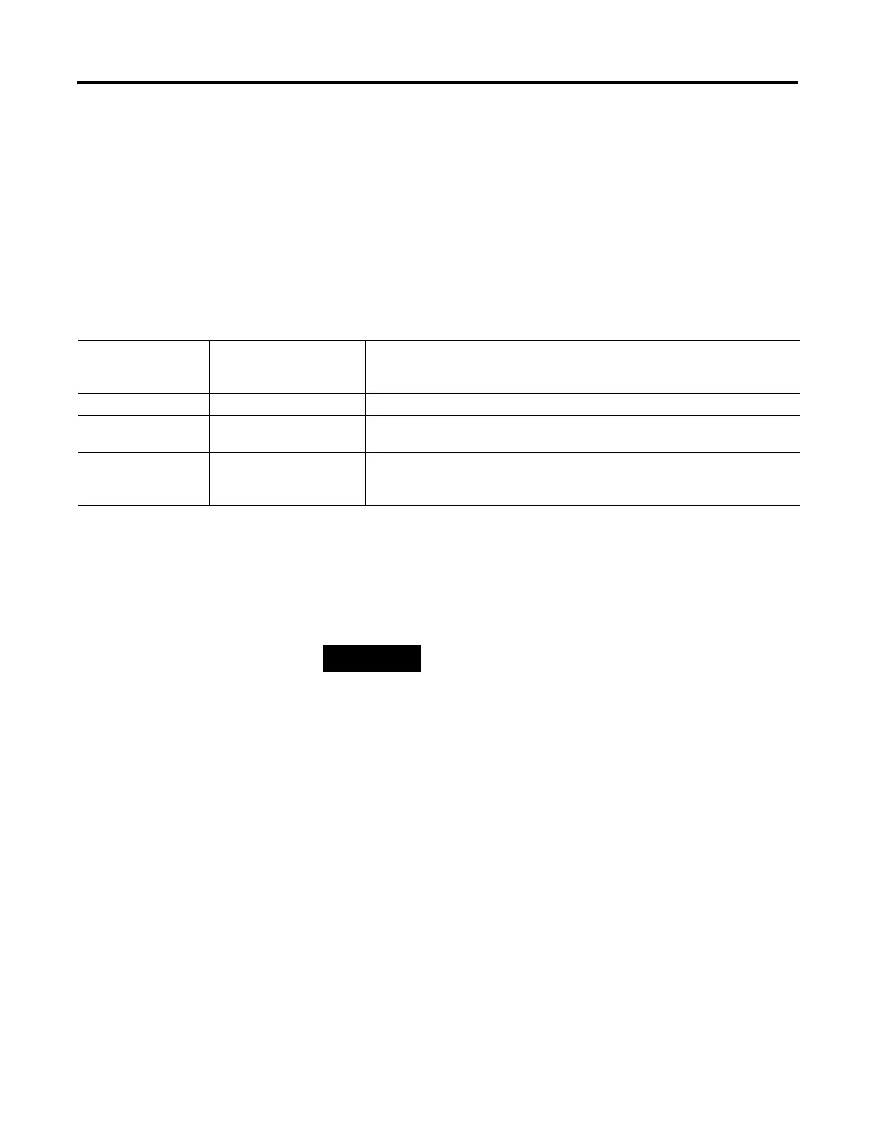
Module Error Types
Error Type Module Error Field Value
Bits 11 through 09
(Binary)
Description
No Errors 000 No error is present. The extended error field holds no additional information.
Hardware Errors 001 General and specific hardware error codes are specified in the extended error
information field.
Configuration Errors 010 Module-specific error codes are indicated in the extended error field. These error
codes correspond to options that you can change directly. For example, the input
range or input filter selection.
If no errors are present in the module error field, the
extended error information field is set to zero.

 Loading...


