EasyManuals Logo

Allen-Bradley MicroLogix 1100 User Manual

Allen-Bradley MicroLogix 1100
256 pages
To Next Page IconTo Next Page
To Previous Page IconTo Previous Page
Page #220 background imageLoading...
Page #220 background image
Publication 1763-UM001E-EN-P - June 2015
218 Connecting to Networks via Ethernet Interface
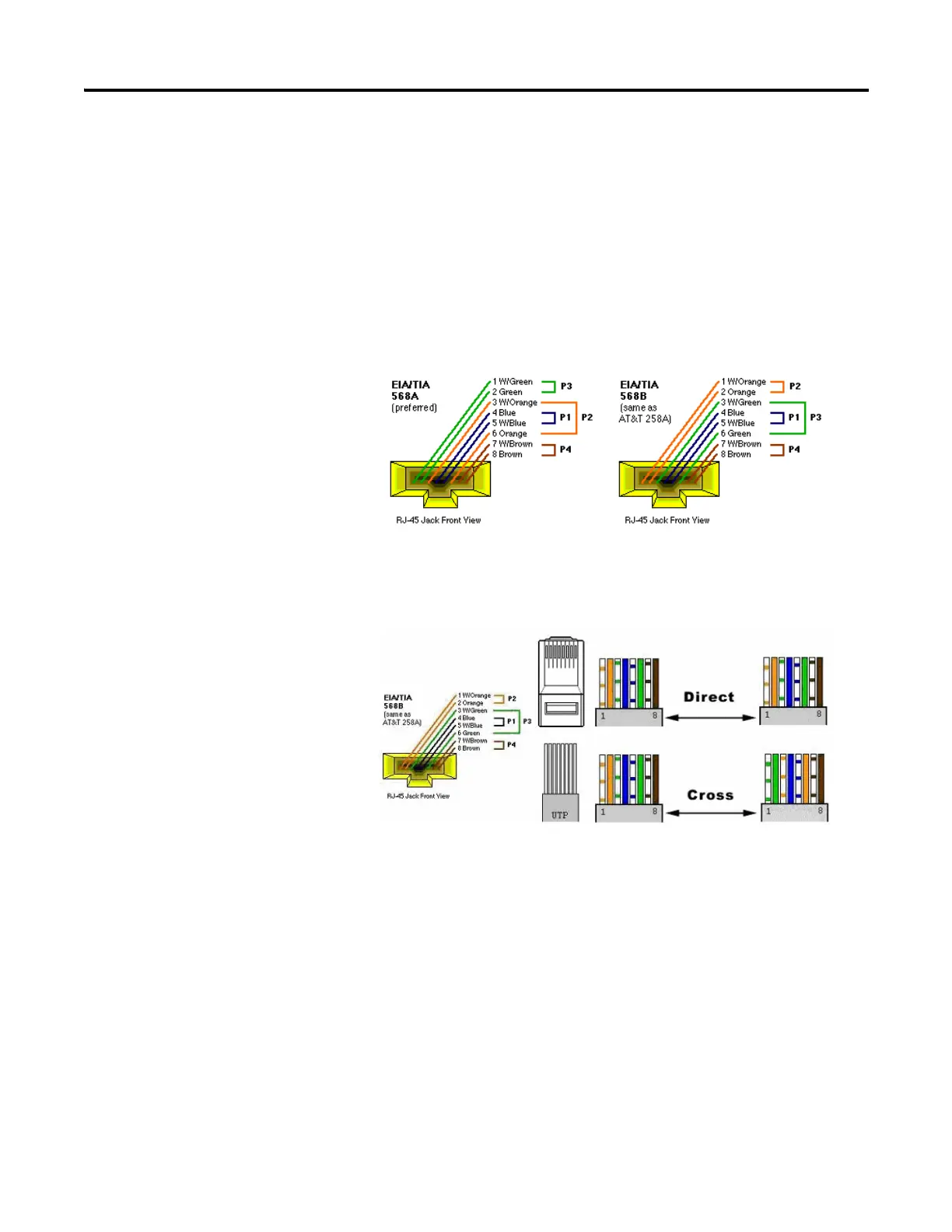
The standard Ethernet cable is terminated in accordance with EIA/TIA 568B
on both ends. The crossover cable is terminated to EIA/TIA 568B at one end
and EIA/TIA 568A at the other, exactly as shown in the two color coded
plugs below.
The following figures show how the TIA/EIA 568A and 568B are to be
terminated. There are four pairs of wires contained in a CAT5 UTP cable.
These pairs of cables are color coded white blue/blue, white orange/orange,
white green/green, white brown/brown, they are also numbered one to four
in the order shown.

Table of Contents

Other manuals for Allen-Bradley MicroLogix 1100

Questions and Answers:

Question and Answer IconNeed help?

Do you have a question about the Allen-Bradley MicroLogix 1100 and is the answer not in the manual?

Allen-Bradley MicroLogix 1100 Specifications

General IconGeneral
Processor32-bit
Programming SoftwareRSLogix 500
MountingDIN rail or panel mount
Power Supply24V DC
TypeCompact PLC
Digital Inputs12
Digital Outputs8
Analog Inputs4 (depending on model)
Analog OutputsOptional with expansion module
Programming LanguageLadder Logic
Operating Temperature0 to 55 °C (32 to 131 °F)
SeriesMicroLogix

Related product manuals