Publication 1763-UM001E-EN-P - June 2015
System Loading and Heat Dissipation 235
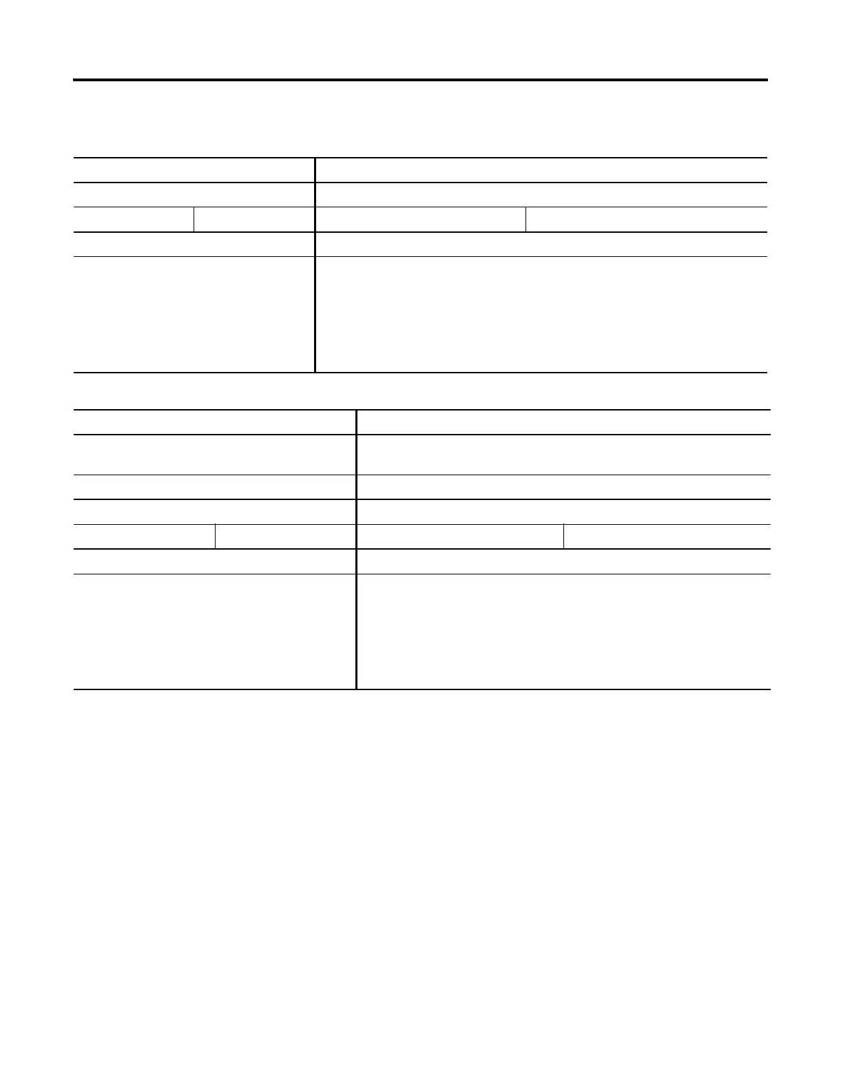
Validating Systems using 1763-L16AWA, 1763-L16BBB, or 1763-L16DWD
Maximum Allowable Values Calculated Values
Current: Current (Subtotal from Table .):
800 mA at 5V DC 700 mA at 24V DC mA at 5V DC mA at 24V DC
System Loading: System Loading:
20.8 W
= (________ mA x 5V) + (________ mA x 24V)
= __________ mW + __________ mW
= __________ mW
= __________ W
Validating Systems using 1763-L16BWA
Maximum Allowable Values Calculated Values
Current for Devices Connected to the +24V DC Sensor
Supply:
Sum of all sensor currents
200 mA at 24V DC mA at 24V DC
Current for MicroLogix Accessories and Expansion I/O: Current (Subtotal from Table .)
800 mA at 5V DC 700 mA at 24V DC mA at 5 V DC mA at 24V DC
System Loading: System Loading:
16.4 W
= (________ mA x 24V) + (________ mA x 5V) + (________ mA x 24V)
= __________ mW + __________ mW + __________ mW
= __________ mW
= __________ W

 Loading...


