EasyManuals Logo

Allen-Bradley MicroLogix 1100 User Manual

Allen-Bradley MicroLogix 1100
256 pages
To Next Page IconTo Next Page
To Previous Page IconTo Previous Page
Page #46 background imageLoading...
Page #46 background image
Publication 1763-UM001E-EN-P - June 2015
44 Wiring Your Controller
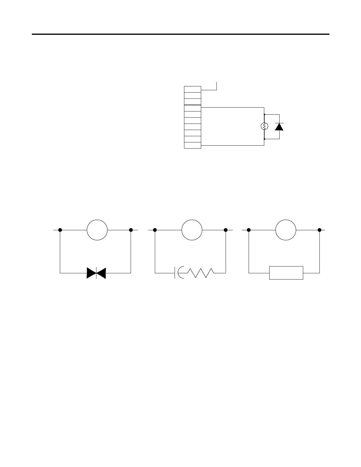
suppressor can also be used. See for recommended suppressors. As shown
below, these surge suppression circuits connect directly across the load device.
Suitable surge suppression methods for inductive AC load devices include a
varistor, an RC network, or an Allen-Bradley surge suppressor, all shown
below. These components must be appropriately rated to suppress the
switching transient characteristic of the particular inductive device. See the
table on 45 for recommended suppressors.
+24V DC
IN4004 Diode
Relay or Solid
State DC Outputs
24V DC common
VAC/DC
Out 0
Out 1
Out 2
Out 3
Out 4
Out 5
Out 6
Out 7
COM
(A surge suppressor
can also be used.)
Surge Suppression for Inductive AC Load Devices
Output Device Output DeviceOutput Device
Varistor
RC Network
Surge
Suppressor

Table of Contents

Other manuals for Allen-Bradley MicroLogix 1100

Questions and Answers:

Question and Answer IconNeed help?

Do you have a question about the Allen-Bradley MicroLogix 1100 and is the answer not in the manual?

Allen-Bradley MicroLogix 1100 Specifications

General IconGeneral
Processor32-bit
Programming SoftwareRSLogix 500
MountingDIN rail or panel mount
Power Supply24V DC
TypeCompact PLC
Digital Inputs12
Digital Outputs8
Analog Inputs4 (depending on model)
Analog OutputsOptional with expansion module
Programming LanguageLadder Logic
Operating Temperature0 to 55 °C (32 to 131 °F)
SeriesMicroLogix

Related product manuals