Publication 1763-UM001E-EN-P - June 2015
48 Wiring Your Controller
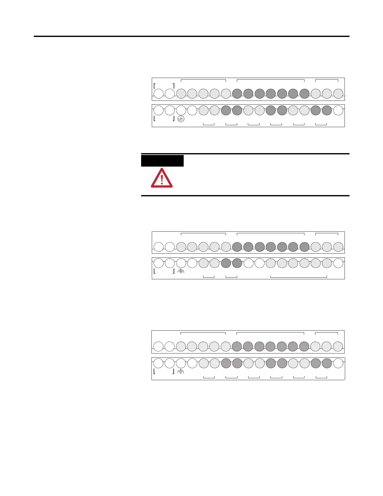
1763-L16BWA
1763-L16BBB
1763-L16DWD
DC
COM-
VAC O/0
VDC
VAC O/1
VDC
VAC O/2
VDC
VAC O/3
VDC
VAC O/4
VDC
VAC O/5
VDC
NOT
USED
NOT
USED
L1 L2/N
100-240 VAC
DC OUT
+ 24V
I/1I/0 I/2 I/3
DC
COM
I/4 I/5
IA
COM
IV1(+) IV2(+)I/6 I/7 I/8 I/9
Input Terminal Block
Output Terminal Block
Group 1 Group 2
G
r
o
u
p
0
G
r
o
u
p
1
G
r
o
u
p
2
G
r
o
u
p
3
G
r
o
u
p
4
G
r
o
u
p
5
Group 0
The 24V DC sensor supply of the 1763-L16BWA should
not be used to power output circuits. It should only be used
to power input devices (e.g. sensors, switches). See Master
Control Relay on page 2-26 for information on MCR
wiring in output circuits.
DC
COM
NOT
USED
VAC O/0
VDC
VAC O/1
VDC
NOT
USED
NOT
USED
DC O/2 O/3
24V+
DC
24V-
O/4 O/5NOT
USED
NOT
USED
+ 24V -
DC IN
NOT
USED
I/1I/0 I/2 I/3
DC
COM
I/4 I/5
IA
COM
IV1(+) IV2(+)I/6 I/7 I/8 I/9
Input Terminal Block
Output Terminal Block
Group 1 Group 2
G
r
o
u
p
0
G
r
o
u
p
1
G
r
o
u
p
2
Group 0
Input Terminal Block
Output Terminal Block
Group 1 Group 2
G
r
o
u
p
0
G
r
o
u
p
1
G
r
o
u
p
2
G
r
o
u
p
3
G
r
o
u
p
4
G
r
o
u
p
5
Group 0
DC
COM
NOT
USED
+ 12/24V -
DC IN
NOT
USED
I/1I/0 I/2 I/3
DC
COM
I/4 I/5
IA
COM
IV1(+) IV2(+)I/6 I/7 I/8 I/9
VAC O/0
VDC
VAC O/1
VDC
VAC O/2
VDC
VAC O/3
VDC
VAC O/4
VDC
VAC O/5
VDC
NOT
USED
NOT
USED

 Loading...


