EasyManuals Logo

Allen-Bradley MicroLogix 1100 User Manual

Allen-Bradley MicroLogix 1100
256 pages
To Next Page IconTo Next Page
To Previous Page IconTo Previous Page
Page #77 background imageLoading...
Page #77 background image
Publication 1763-UM001E-EN-P - June 2015
Communication Connections 75
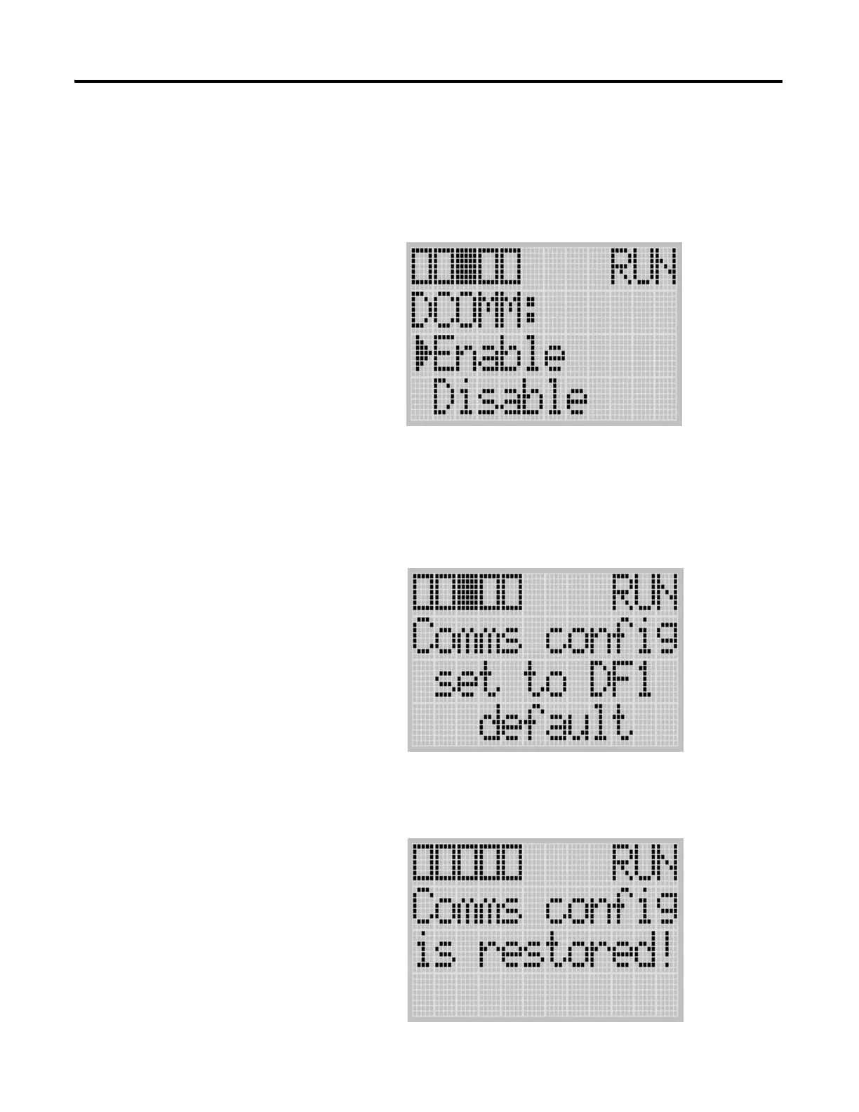
If the communication configuration is set to the default communication
mode, the DCOMM Configuration screen is displayed as shown below.
The DCOMM status indicator is displayed in solid rectangle.
5. Use the up arrow to change the indicator position so that it is pointing
to Enable.Press the OK key to change to the default communication
mode. The DCOMM Mode Change Notification screen is displayed, as
shown below. It indicates that the communication configuration is
changed to the default communication mode. The DCOMM status
indicator is displayed in solid rectangle.
If you change to the user-defined configuration from the default
configuration mode by selecting Disable and pressing the OK key, the
DCOMM Mode Change Notification will be displayed as shown below.
COMM0
COMM1
DCOM
M
BA
T
.
L
O
U-
M
SG

Table of Contents

Other manuals for Allen-Bradley MicroLogix 1100

Questions and Answers:

Question and Answer IconNeed help?

Do you have a question about the Allen-Bradley MicroLogix 1100 and is the answer not in the manual?

Allen-Bradley MicroLogix 1100 Specifications

General IconGeneral
Processor32-bit
Programming SoftwareRSLogix 500
MountingDIN rail or panel mount
Power Supply24V DC
TypeCompact PLC
Digital Inputs12
Digital Outputs8
Analog Inputs4 (depending on model)
Analog OutputsOptional with expansion module
Programming LanguageLadder Logic
Operating Temperature0 to 55 °C (32 to 131 °F)
SeriesMicroLogix

Related product manuals