EasyManuals Logo

Allen-Bradley MicroLogix 1100 User Manual

Allen-Bradley MicroLogix 1100
256 pages
To Next Page IconTo Next Page
To Previous Page IconTo Previous Page
Page #81 background imageLoading...
Page #81 background image
Publication 1763-UM001E-EN-P - June 2015
Communication Connections 79
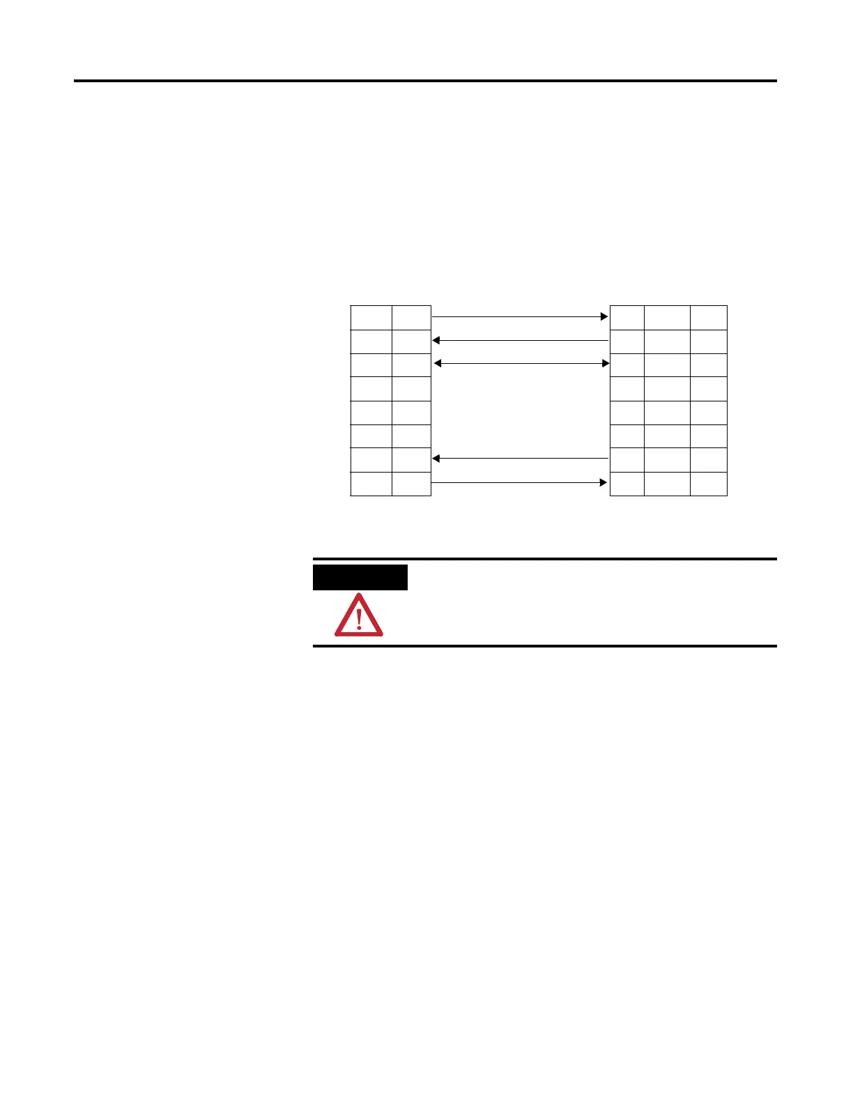
MicroLogix 1100 Channel 0 to Modem Cable Pinout
When connecting MicroLogix 1100 Channel 0 to a modem using an RS-232
cable, the maximum that the cable length may be extended is 15.24 m (50 ft).
ATTENTION
Do not connect pin 1,8, and 5. This connection will
cause damage to the RS-232/485 communication port
(channel 0) of the MicroLogix 1100 and/or the
controller itself.
DTE Device
(MicroLogix
1100
Channel 0)
DCE Device
(Modem,
PanelView,
etc.)
8-Pin 25-Pin 9-Pin
7 TXD TXD 2 3
4 RXD RXD 3 2
2GND GND7 5
1B(+) DCD8 1
8A(-) DTR204
5N.C. DSR6 6
6 CTS CTS 5 8
3 RTS RTS 4 7

Table of Contents

Other manuals for Allen-Bradley MicroLogix 1100

Questions and Answers:

Question and Answer IconNeed help?

Do you have a question about the Allen-Bradley MicroLogix 1100 and is the answer not in the manual?

Allen-Bradley MicroLogix 1100 Specifications

General IconGeneral
Processor32-bit
Programming SoftwareRSLogix 500
MountingDIN rail or panel mount
Power Supply24V DC
TypeCompact PLC
Digital Inputs12
Digital Outputs8
Analog Inputs4 (depending on model)
Analog OutputsOptional with expansion module
Programming LanguageLadder Logic
Operating Temperature0 to 55 °C (32 to 131 °F)
SeriesMicroLogix

Related product manuals