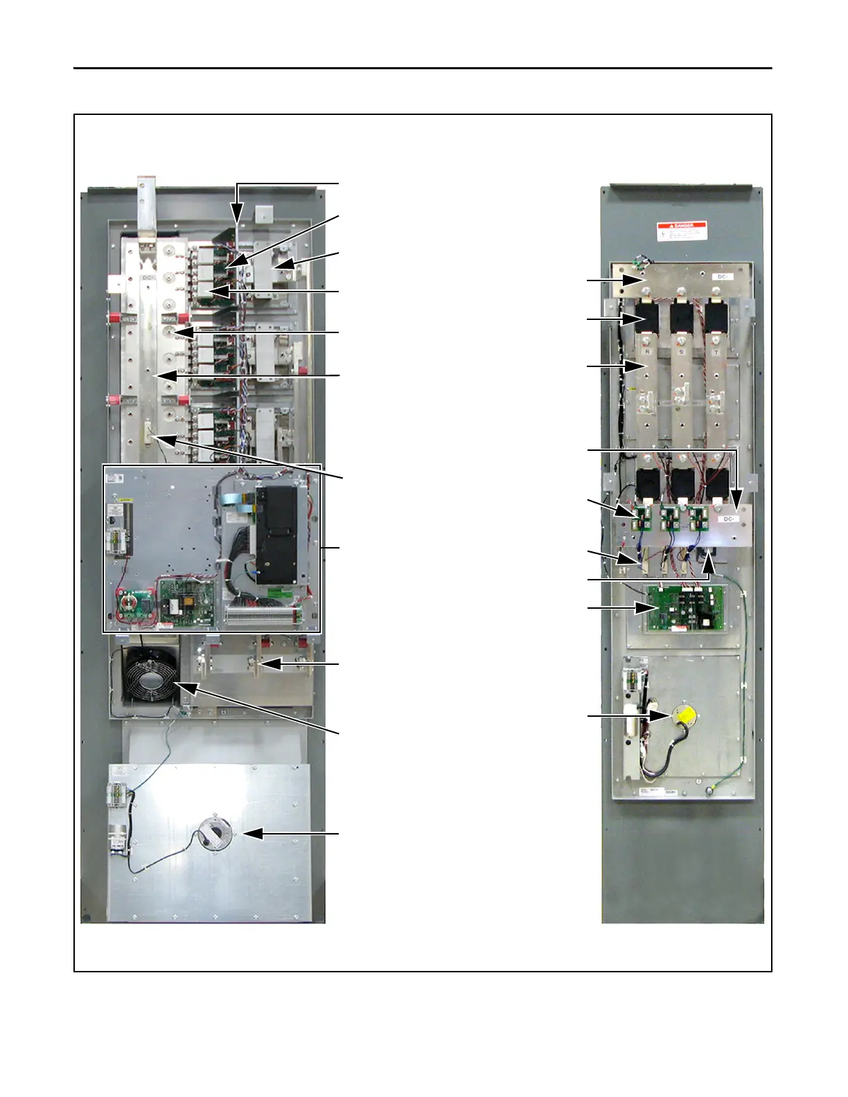
EasyManuals Logo

Allen-Bradley powerflex 700 Installation Instructions

Allen-Bradley powerflex 700
96 pages
To Next Page IconTo Next Page
To Previous Page IconTo Previous Page
Page #16 background imageLoading...
Page #16 background image
16 Rockwell Automation Publication 20B-IN026C-EN-P - October 2015
Chapter 1 Component Diagrams and Torque Specifications
Figure 1 - Frame 10 Assembly Components
Inverter Assembly
(DC input and AC input with converter assembly)
Converter Assembly
(AC input only)
Heatsink Fan Assembly
Stacking Panel
SCR Modules (6)
Motor Busbars (3)
MOV Suppressor
AC Busbars (3)
Snubber Boards (3)
Capacitor Bank Fan
Balancing Resistor (Old
Resistor Style Shown)
Precharge Board
Snubber
Resistors (3)
DC- Busbar
DC+ Busbar
IGBT Snubber Capacitors (9)
Transitional Busbar Assembly
(4 pcs: DC+ Busbar, DC- Busbar,
Upper Capbus Support, and
Lower Capbus Support)
Gate Interface Boards (3)
Current Transducers (3)
DC Bus Capacitors (26)
IGBT Interface Boards (3)
Heatsink Fan Assembly
(IP00, NEMA/UL Type Open Assemblies Shown)

Table of Contents

Other manuals for Allen-Bradley powerflex 700

Questions and Answers:

Question and Answer IconNeed help?

Do you have a question about the Allen-Bradley powerflex 700 and is the answer not in the manual?

Allen-Bradley powerflex 700 Specifications

General IconGeneral
SeriesPowerFlex 700
CategoryAC Drive
Input Voltage200-240V AC, 380-480V AC, 500-600V AC
EnclosureType 1
Control MethodSensorless Vector
CommunicationEtherNet/IP, ControlNet, DeviceNet, PROFIBUS DP, Modbus

Related product manuals