EasyManuals Logo

Allen-Bradley powerflex 700 Installation Instructions

Allen-Bradley powerflex 700
96 pages
To Next Page IconTo Next Page
To Previous Page IconTo Previous Page
Page #17 background imageLoading...
Page #17 background image
Rockwell Automation Publication 20B-IN026C-EN-P - October 2015 17
Component Diagrams and Torque Specifications Chapter 1
Figure 2 - Frame 10 Assembly Busbar Locations
R
L1
S
L2
T
L3
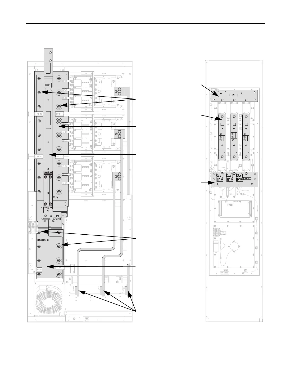
Inverter Assembly Converter Assembly
Motor Busbars
Lower DC Bus Capacitors (8)
Inverter Assembly Shown With
Stacking Panel Removed
Upper DC Bus Capacitors (18)
Lower Capbus Support
Transitional Busbar Assembly
(4 pcs: DC+ Busbar, DC- Busbar,
Upper Capbus Support, and
Lower Capbus Support)
Upper Capbus Support
AC Busbars (3)
DC- Busbar
DC+ Busbar
U
W
V

Table of Contents

Other manuals for Allen-Bradley powerflex 700

Questions and Answers:

Question and Answer IconNeed help?

Do you have a question about the Allen-Bradley powerflex 700 and is the answer not in the manual?

Allen-Bradley powerflex 700 Specifications

General IconGeneral
SeriesPowerFlex 700
CategoryAC Drive
Input Voltage200-240V AC, 380-480V AC, 500-600V AC
EnclosureType 1
Control MethodSensorless Vector
CommunicationEtherNet/IP, ControlNet, DeviceNet, PROFIBUS DP, Modbus

Related product manuals