18 Rockwell Automation Publication 20B-IN026C-EN-P - October 2015
Chapter 1 Component Diagrams and Torque Specifications
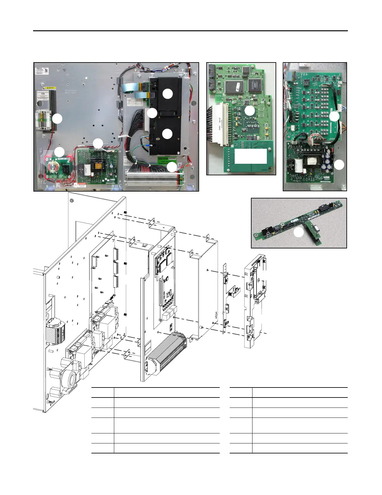
Figure 3 - Circuit Boards on Inverter Assembly
No. Description No. Description
1 HIM Cradle/Communication Board 6 Power Interface Board
2 Communication Board Slots (for optional devices) 7 Switch Mode Power Supply Board
3 T-Comm Board 8 24V Power Supply Board for Current Transducers
(CTs)
4 Main Control Board 9 DC Bus Filter Board
5 TB11 10 TB9
Communications
Panel
Main Control Panel
Stacking
Panel
Encoder Board
(optional)

 Loading...


