Rockwell Automation Publication 20B-IN026C-EN-P - October 2015 73
Inverter Assembly Component Replacement Procedures Chapter 3
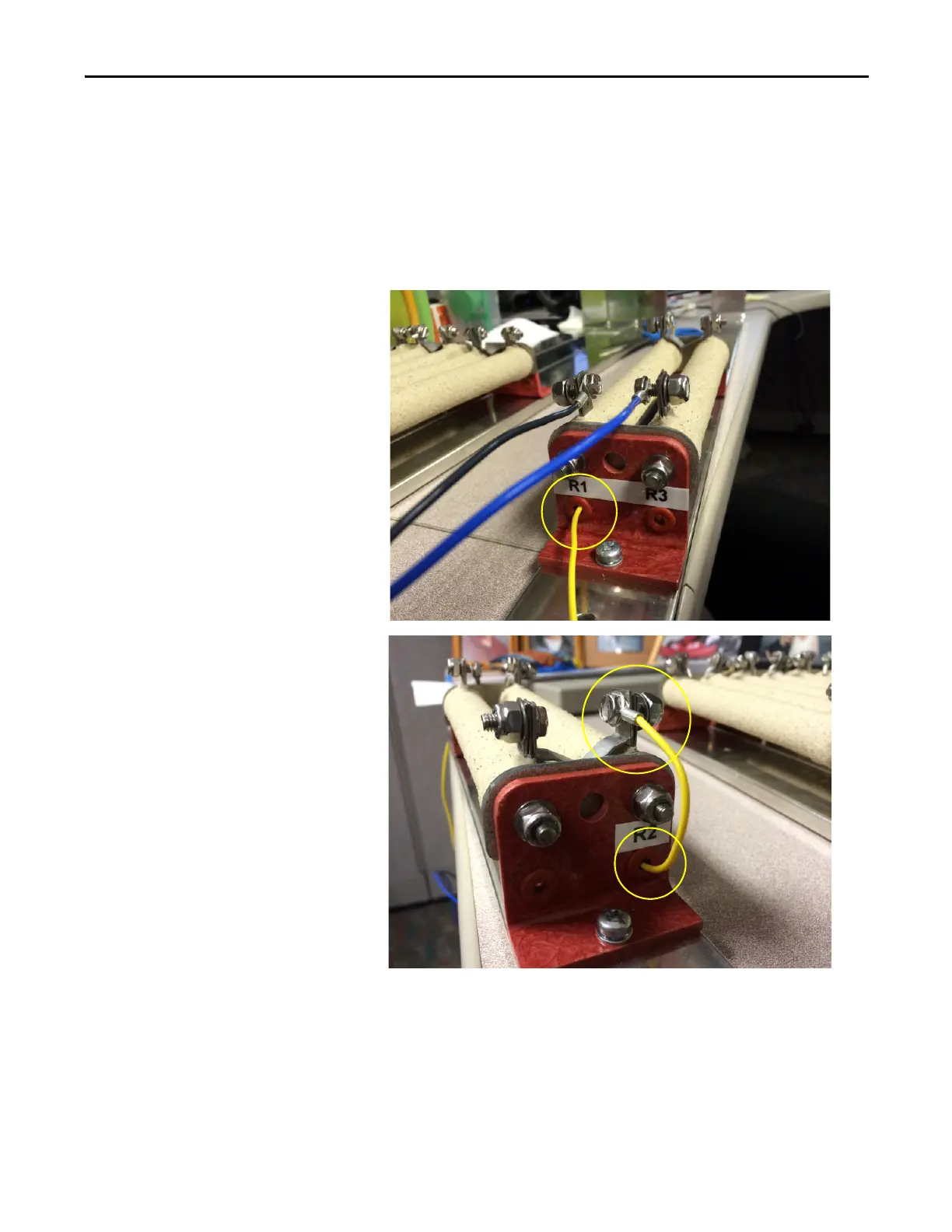
4. Verify that the yellow resistor wire is long enough to connect to the left
terminal (R2) on the top of the resistor assembly. To do so, route the wire
through the bottom and out of the top of the holes in the insulator
material on the resistor assembly (as shown in the following images).
Note: If the yellow resistor wire is not long enough to reach the top
terminal (R2) when routed through the assembly, it is acceptable to leave
the wire outside of the assembly to make the connection.

 Loading...


