72 Rockwell Automation Publication 20B-IN026C-EN-P - October 2015
Chapter 3 Inverter Assembly Component Replacement Procedures
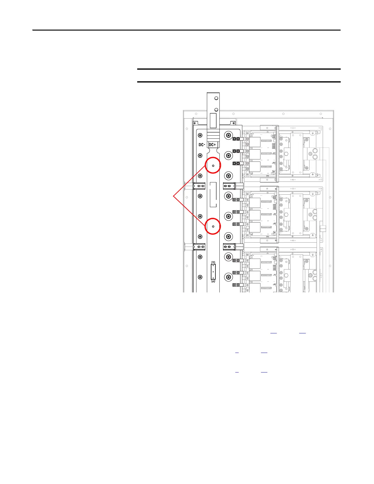
10. While holding the bus bar, remove the nuts that secure the bus bar to the
chassis and remove the bus bar.
Install Components
1. Install the set screws and nuts removed in step 10 on page 72. Tighten the
nuts to 5.65 N•m (50 lb•in).
2. Install the bolts removed in step 9
on page 71. Tighten the bolts to 23.5
N•m (208 lb•in).
3. Install the bolts removed in step 8
on page 70. Tighten the bolts to 23.5
N•m (208 lb•in).
The set screws can come out when a nut is removed.

 Loading...


