Publication 1752-UM001A-EN-P - October 2006
Configure Local I/O 57
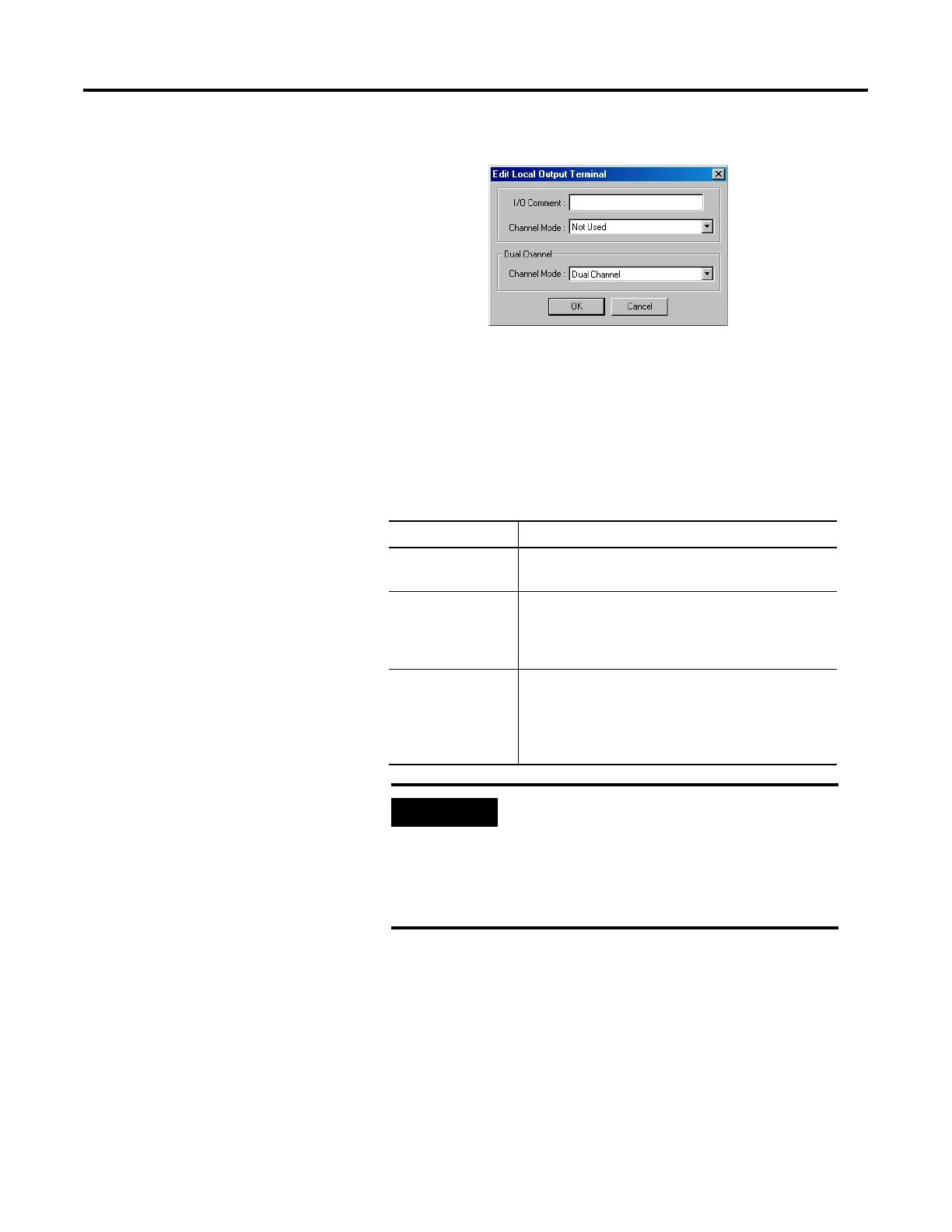
4. Select a safety output terminal and click Edit.
5. Type an I/O Comment.
The I/O comment typed here is used as an I/O tag name in the
Logic Editor.
6. Set the Channel Mode for the safety output.
Output Channel Mode Settings
Channel Mode Description
Not used The output terminal is not connected to an output
device.
Safety A test pulse is not sent when the output is on. When
the output is off, short circuits with the power supply
line can be detected. Ground faults can also be
detected.
Safety Pulse Test A test pulse is sent when the output is on. This
enables detection of short circuits with the power
supply line (positive side) whether the output is on or
off. Ground faults and short circuits between output
signals can also be detected.
IMPORTANT
If a safety pulse test is set, an off pulse signal
(pulse width 580 μs) is output to diagnose the
output circuit when the safety output turns on.
Check the input response time of the control device
to make sure this output pulse will not cause
malfunctions.

 Loading...


