136 Rockwell Automation Publication 1560F-UM001A-EN-P - June 2019
Chapter 7 Communications
HIM Keypad and Displays
The SMC-50 control module can be programmed with the optional Bulletin
20-HIM-A6 LCD display. Parameters are organized in a multi-level menu
structure and are divided into programming groups.
Connecting the HIM to the Control Module
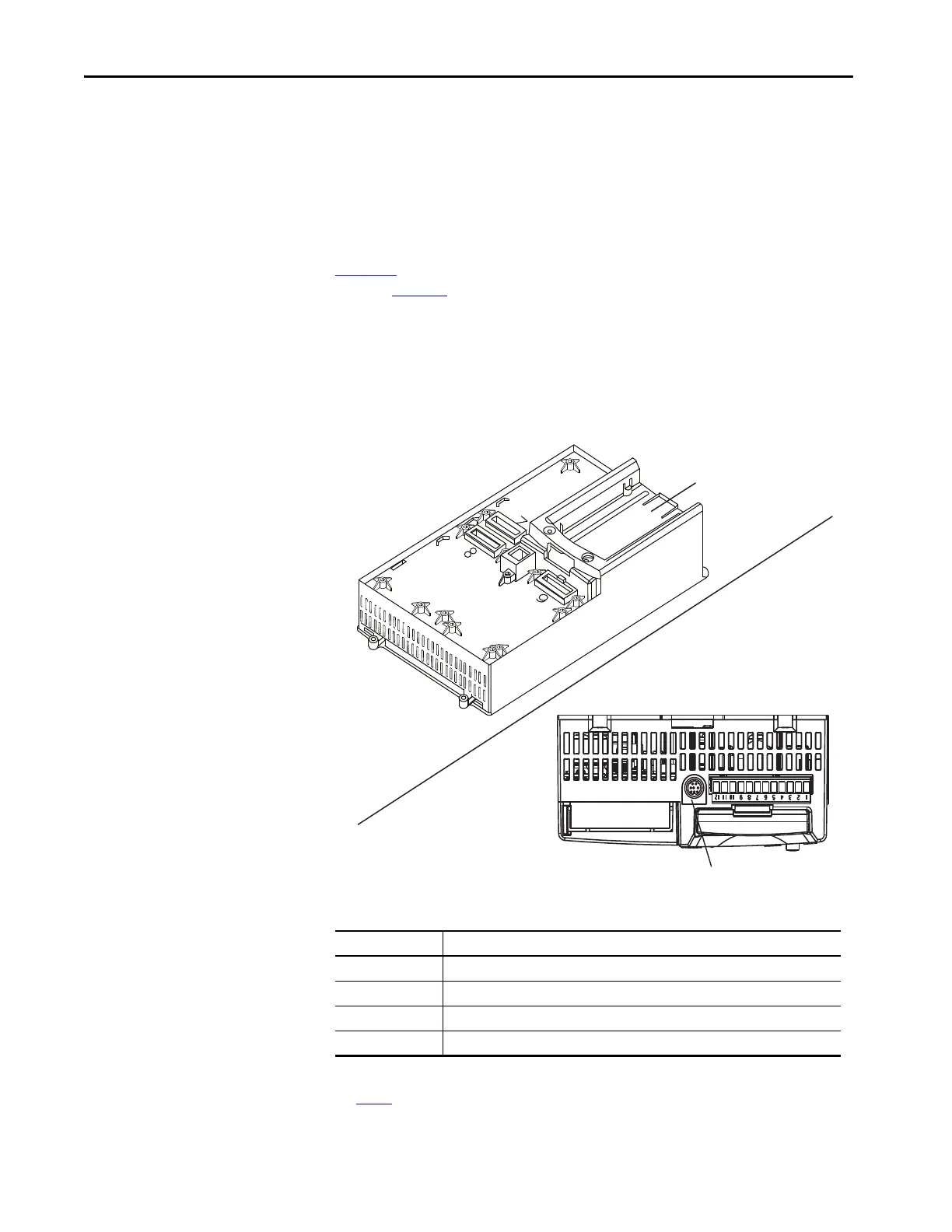
Figure 47 shows how to connect a HIM and DPI device to the SMC-50 control
module. Table 46
provides a description of each port.
See the control wiring diagram that enables start-stop control from a HIM.
Figure 47 - SMC-50 Control Module with a HIM
Table 46 - Description of Ports
TIP The SMC-50 controller only supports the use of DPI communication modules
and DPI 20-HIM-A6 Modules.
DPI Port Number Source
1 Front-Mounted HIM (HIM Bezel)
2 Remote DPI (top of SMC-50 control module)
3 Remote DPI (top of SMC-50 control module with splitter)
4
(1)
(1) When using a 20-COMM-x network communication module, it must physically be located in control module hardware port 9.
However, its DPI Port Number assignment is 4. The cable connection for the DPI Port 4 is located below the HIM bezel (see
Figure 47
).
20-COMM-x Module
Front View
Top View
HIM Bezel Port
DPI Port 2
(Port 2 and 3 if you use a splitter)

 Loading...


