Rockwell Automation Publication 1560F-UM001A-EN-P - June 2019 53
Installation Chapter 2
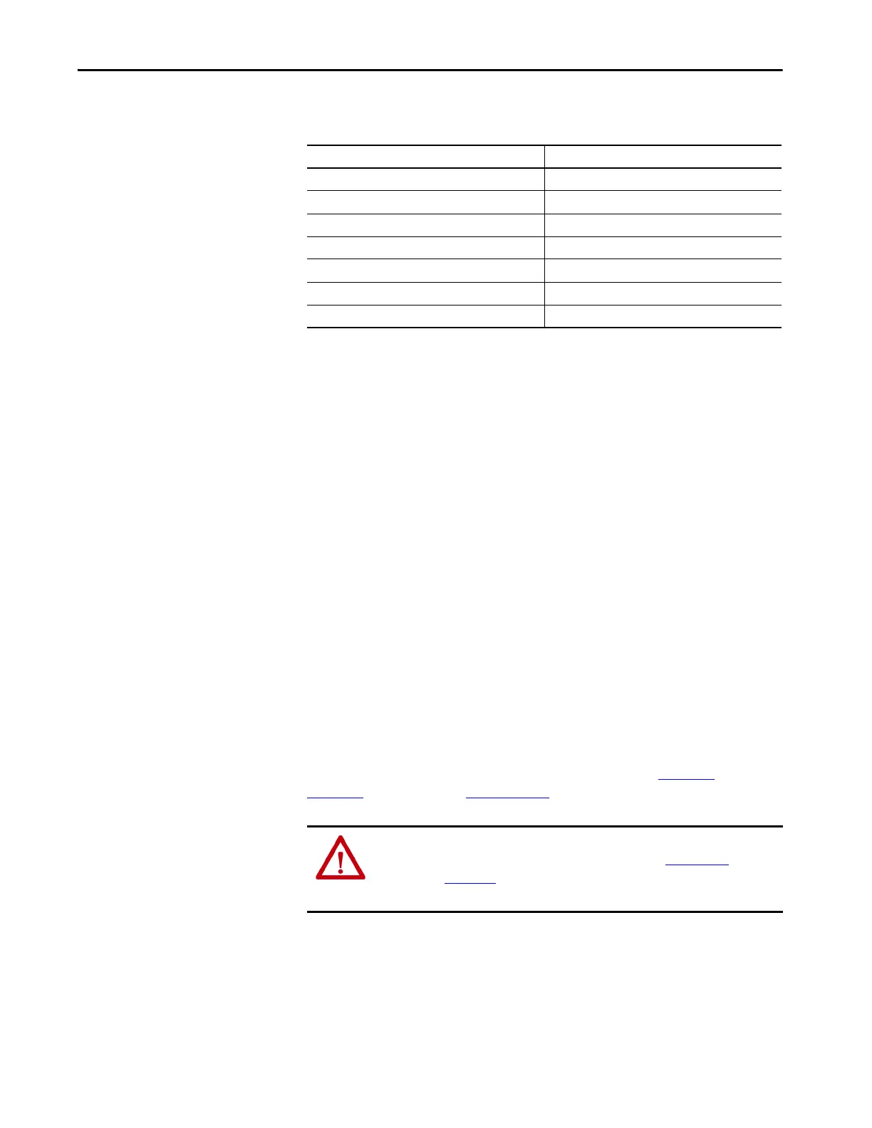
Recommended Torque
Values
When reinstalling components or when reassembling the cabinet, tighten the
following bolt sizes to the specified torque values:
Power Connections
The controller requires a three-phase supply and an equipment grounding
conductor to earth ground. A neutral conductor of the three-phase supply is not
necessary and is usually not routed to the controller. Three-phase wiring will
connect the controller to the motor.
Bulletin 1562F
The Bulletin 1562F unit is available in two main configurations:
1. A modified two-high cabinet (180/360 A, 2400…4160V)
2. A combination of a one-high full voltage non-reversing (FVNR) cabinet
and a 1560F unit (600 A, 2400…4160V, and 180/360/600 A,
5500…6900V)
To make power connections for a two-high cabinet, refer to Figure 28
to
Figure 30
, and publication 1500-UM055 (Chapter 2).
To make power connections for a one-high FVNR cabinet and a 1560F unit,
proceed as follows:
• Make line connections within the one-high cabinet
• Make load connections at the primary load current transformer terminals
Hardware Recommended Torque
1/4 in. (M6) 8 N•m (6 lb•ft)
5/16 in. (M8) 15 N•m (11 lb•ft)
3/8 in. (M10) 27 N•m (20 lb•ft)
1/2 in. (M12) 65 N•m (48 lb•ft)
Control Wire Terminals 2.5…4.0 N•m (2.0…3.3 lb•in)
CLGD Power Assembly Terminals 5.6 N•m (50 lb•in)
SMC-50 Control Module Terminals 0.6 N•m (5 lb•in)
TIP For 3/8 in. hardware in the “T”-slots of aluminum heatsinks, the recommended
torque is 22 N•m (16 lb•ft). Do not overtorque these connections as the slots
will be damaged and the connection will be compromised.
ATTENTION: Bulletin 1562F units provided with an arc resistant enclosure must
be installed in accordance with instructions in publication 1500-UM055
. See
publication MV-QS050
for level floor surface requirements. Failure to do so may
result in damage to equipment or personal injury.

 Loading...


