Rockwell Automation Publication 1560F-UM001A-EN-P - June 2019 167
Troubleshooting Chapter 9
Voltage Sensing Board
Replacement
1. Ensure there is no power to the equipment.
2. Mark the position of the ribbon cable and wires.
3. Remove the screws and lift the ring lugs from the terminals to remove the
wires.
4. Release the locking mechanism located on each side of the ribbon cable
connector and pull the ribbon cable straight out to prevent bending the
pins.
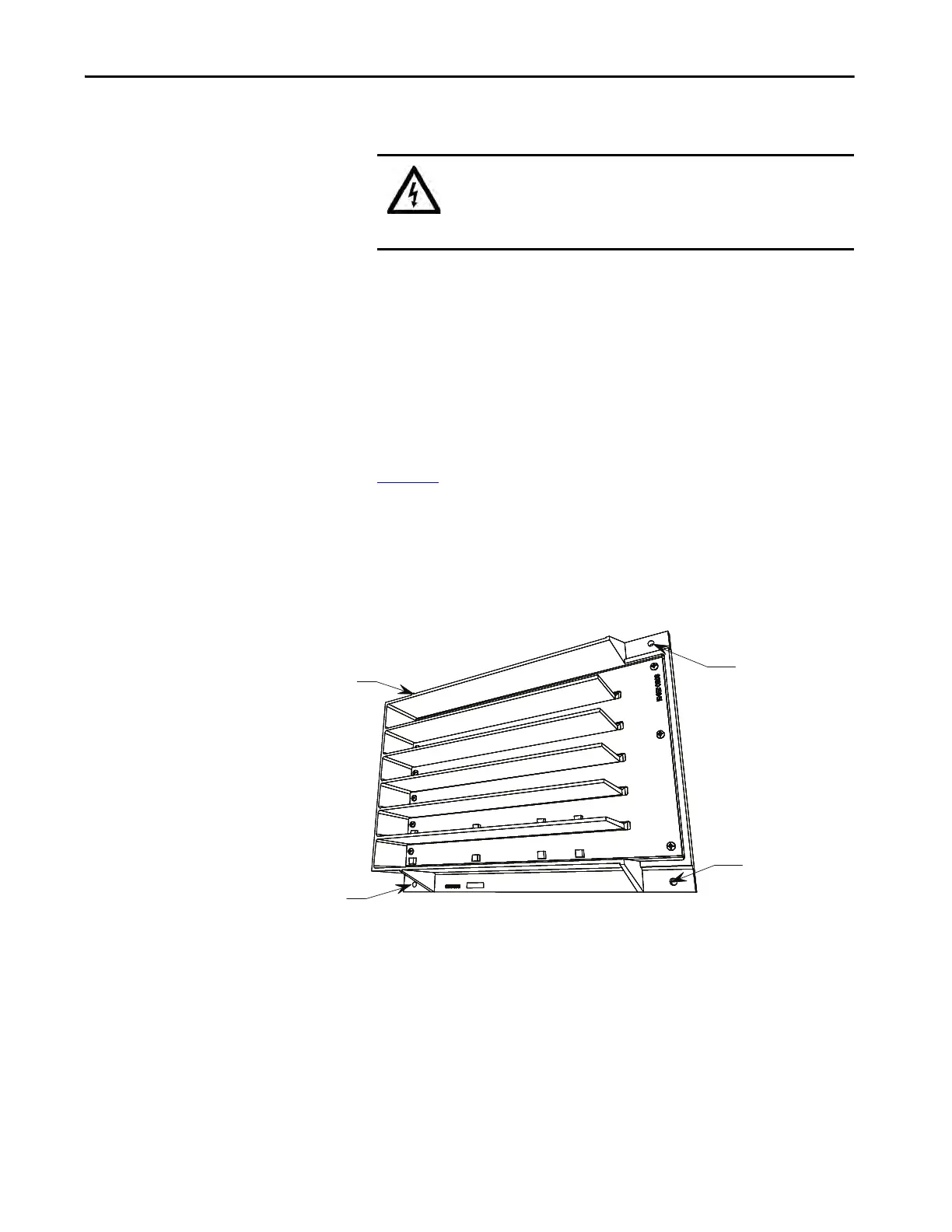
5. Remove the 4 nuts that secure the assembly to the side panel.
6. Replace with the new assembly securing with all 4 nuts and washers. (See
Figure 50
.)
7. Replace ring lugs on terminals. Plug in ribbon cable making sure that it is
positioned properly and fitting is secure (locking mechanism is engaged).
8. For personnel and equipment safety, ensure both grounding connections
are reconnected to the sensing board.
Figure 50 - Sensing Board with mounting hardware placement
SHOCK HAZARD: To prevent electrical shock, ensure the main power
has been disconnected before working on the sensing board. Verify that
all circuits are voltage free using a hot stick or appropriate high voltage-
measuring device. Failure to do so may result in injury or death.
Mounting Hardware
Mounting Hardware
Mounting Hardware
Mounting Hardware

 Loading...


