Rockwell Automation Publication 1560F-UM001A-EN-P - June 2019 37
Product Overview Chapter 1
Status Indication
All auxiliary contacts can be programmed as NO or NC. The contact without a
suffix indicates a NO state (Normal). A contact followed by NC indicates a
normally closed state (Normal NC).
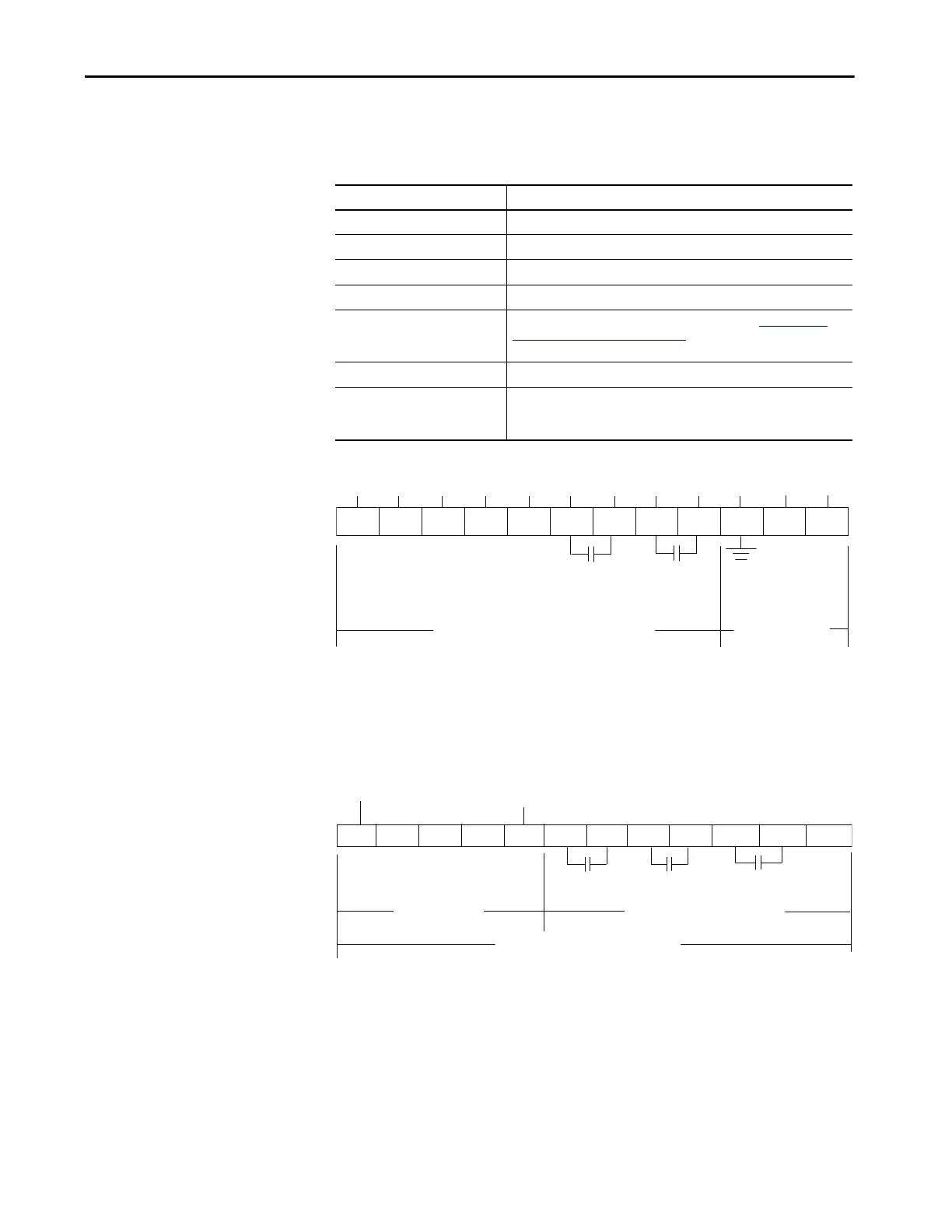
Figure 20 - Control Terminals - SMC-50 Control Module
• The Aux #1 contact is always programmed for External Bypass (NO) to
control the bypass contactor in MV applications.
• The Aux #2 contact is always configured as Normal (NO) to control the
line contactor for MV applications.
• In1 DC is typically programmed for Emergency Run in MV Applications
Figure 21 - Control Terminals - 150-SM4 Digital I/O Card (Slot 7)
• Input #A1 is typically programmed for ‘Start’ in MV applications.
• Input #A2 is typically programmed for ‘Stop Option’ in MV applications.
• Input #A3 is typically programmed for ‘Coast’ in MV applications.
• Aux #A1 is typically programmed for ‘Fault’ in MV applications.
State Description
Normal/Normal NC The contact state changes when the unit receives a Start/Stop signal.
Up-to-Speed/Up-to-Speed NC The contact state changes when the motor approaches rated speed.
Alarm/Alarm NC The contact state changes when an Alarm condition is detected.
Fault/Fault NC The contact state changes when a Fault condition is detected.
Network Control/Network Control NC The contact state is controlled over the network. (Refer to SMC-50 Control
Module—Bit Identification on page 140, which describes logic command
word to control auxiliary outputs).
External Bypass This contact controls the Bypass contactor for MV applications.
External Brake The contact state changes when the external braking command is active and
opens when it is not active Aux. Control: The contact state changes when an
auxiliary output is configured for Aux. Control.
+L1-L2
12 11 10 9 8
7
5
6
421 3
Control Power and
Ground
Internal +24V DC
In1 DC
In2 DC
Enable I/O
Internal DC
Common
Aux 2
Aux 1
Control Module Standard I/O
NC
A1 A2 A3 A4 A5 A6 A7 A8 A9 A10 A11 A12
AC Inputs
Auxiliary Relay Outputs
150-SM4 Option I/O Module
AuxA2
AuxA1
AuxA3
InA2
InA3
InA1
InA4
InCOM

 Loading...


