264 Rockwell Automation Publication 1560F-UM001A-EN-P - June 2019
Appendix E ArcShield Plenum Installation Instructions
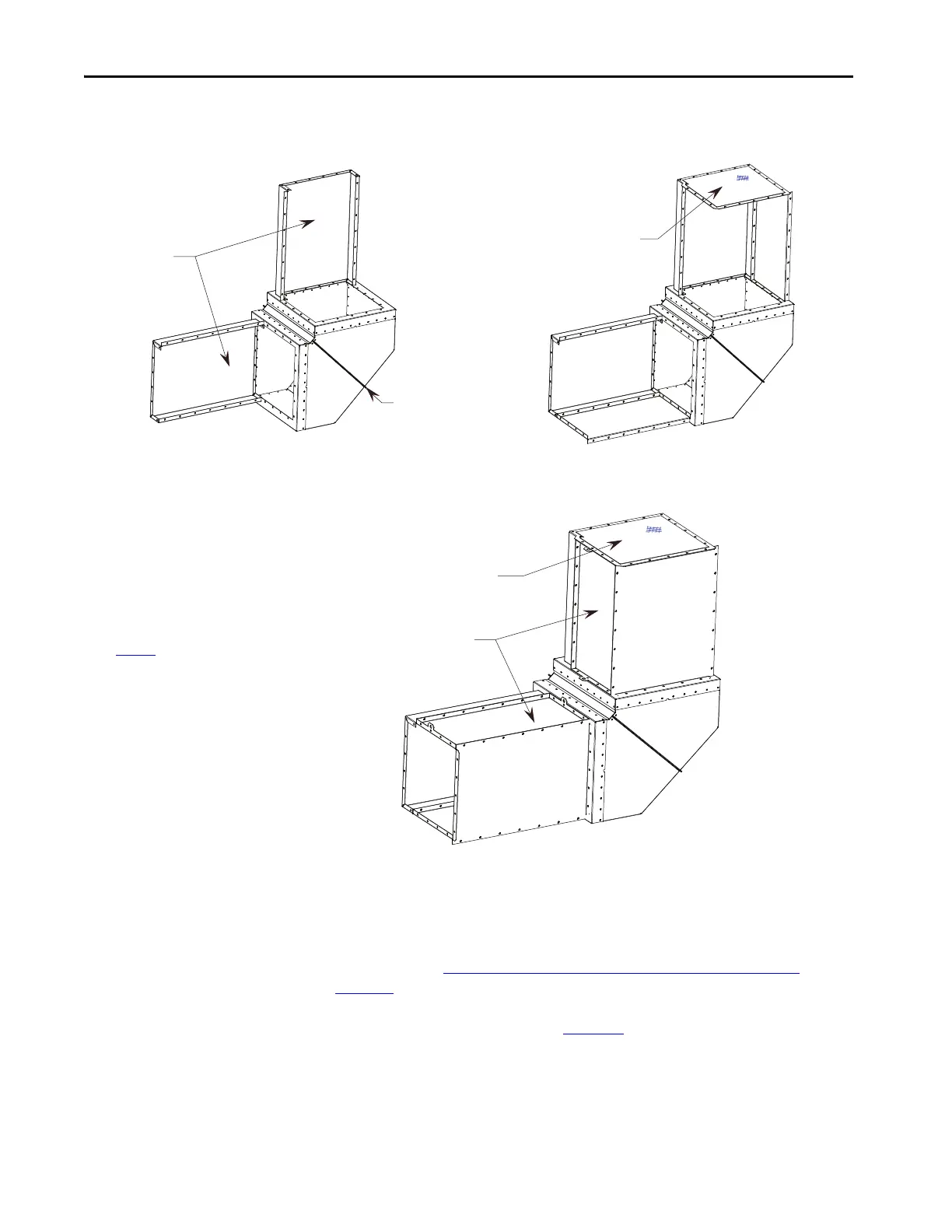
Figure 96 - 90° Elbow Section Assembly, Step 5C (Front View)
STEP 6 – Mounting
Extension/Elbow to Plenum
“Line-up”
As referred to in STEP 4 – Closing the Front of the Plenum Sections on
page 263, the last Plenum at the exhaust side of the line-up has the front duct
section removed. This allows access to fastener holes in order to mount the
Extension/Elbow components (see Figure 97
).
Figure 94 - 90° Elbow Section Assembly, Step 5A (Front View) Figure 95 - 90° Elbow Section Assembly, Step 5B (Front View)
36" Extensions
2-piece 90 deg.
Elbow Section
The Extension components are attached to the Elbow
Section using 5/16-inch Hardware.
Figure 96
illustrates what the Extension/Elbow Assembly
should resemble when finished.
36" Extensions
Screen Cover Plate
TIP Use silicone caulking generously to fill any air gaps once the Plenum has been
securely mounted in place.

 Loading...


