138 Rockwell Automation Publication 1560F-UM001A-EN-P - June 2019
Chapter 7 Communications
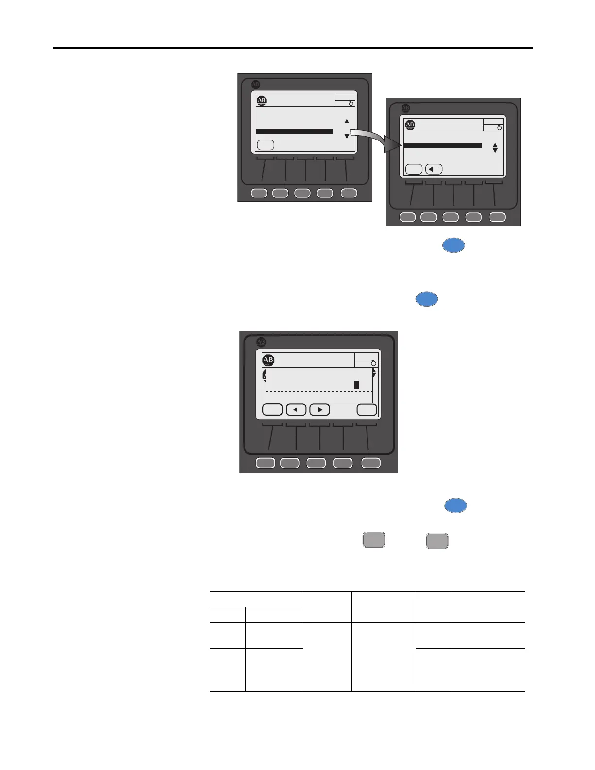
5. With Comm Mask selected/highlighted, press the key. The
GROUP Comm Masks screen appears with the associated Logic Mask
Action selected.
6. Select/highlight Logic Mask, then press the key. The Edit Logic
Mask screen with bit field appears.
7. Press the EDIT key to modify the settings, then use the left or right arrow
to select the desired bit, 1 through 4, then press the key.
To enable motor control, press or press to disable motor
control from the selected DPI port, then press EDIT.
Table 47 - Logic Mask and Logic Mask Active Parameter Specifications
Parameter Bit Number DPI Assignment Access Units [default]
Number Name
148 Logic Mask 0 - NA
1
2
3
4
5 - 15 NA
Port 0 - NA
Port 1
Port 2
Port 3
Port 4
Port 5 - 15 NA
R/W Bit = 0 [disabled]
Bit = 1 enabled
149 Logic Mask Act R Bit = 0 [disabled]
Bit = 1 enabled
[Follows Logic Mask]
PROPERTIES
AUTO
Stopped
0 Amps
Allen-Bradley
ESC
Port 00 Param File-Group
F
FILE Monitoring
FILE Set Up
FILE Motor Protection
FILE Communications
FILE Utility
PROPERTIES
AUTO
Stopped
0 Amps
Allen-Bradley
ESC
Port 00 Param File-Group
F
FILE Communications
GROUP Comm Masks
GROUP Data Links
5
PROPERTIES
AUTO
Stopped
0 Amps
Allen-Bradley
ESC
ENTER
Bit 02
Edit Logic Mask
x000 0000 0000 0000
F

 Loading...


