A IN
B
RR1 RR2
OV1
OV2 OV3 OV4
S1 S2 S3 S4
RS1 RS2CS1 CS2
C1
C2 C3 C4
OV S C
TEST
CLGD
CT
RX1 TX1
G C T
L1
L2
L3
CL
CT2
CT1
CT3
MTR
A OUT
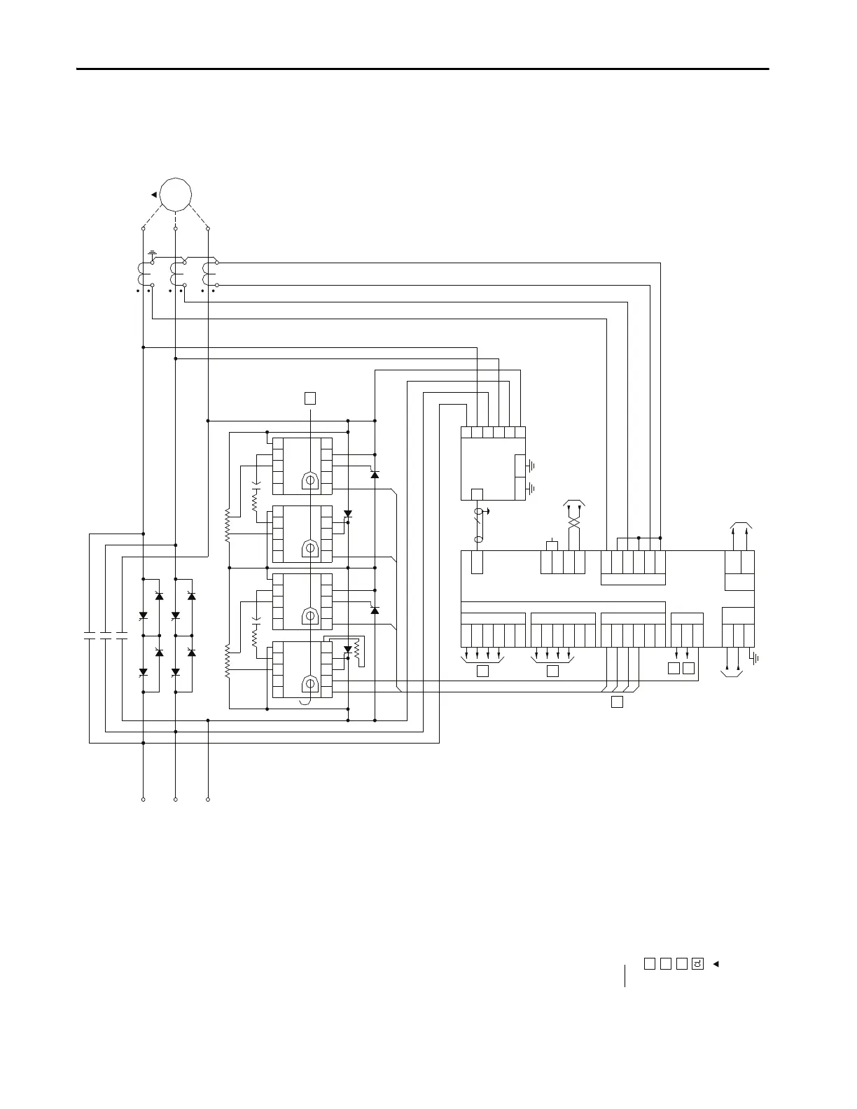
CAUTION MAXIMUM TWO STARTS PER HOUR WITH A MINIMUM OF FIVE
MINUTES BETWEEN STARTS.
WIRE CONNECTIONS FOR PHASE A
WIRE CONNECTIONS FOR PHASE B
CONNECTIONS SHOWN FOR PHASE C
CURRENT LOOP CONDUCTORS PASS THROUGH THE C.T.'S ON THE
GATE DRIVER BOARDS (CLGD)
REMOTE EQUIPMENT
SMC-50INTERFACE BOARD IB VOLTAGE SENSING BOARD
VSB
GATE TRANSMITTERS
PHASE A PHASE B
CT INPUTS
TX1
TX2
TX7
TX8
TX13
TX14
TX3
TX4
TX9
TX10
TX15
TX16
TX5
TX6
TX11
TX12
TX17
TX18
RX1
RX2
RX3
TEMP.
POWER
IN
POWER
OUT
FROM CONTROL
CIRCUIT
TB1
L1
L2/N
G
TB7
TO SMC-50
TB5
A- 6
A+ 5
B- 4
B+ 3
C- 2
C+ 1
TB6
TB21
VSB
GDPS FROM CLT
24C
L1
T1
L2
T2
L3
T3
GND1 GND2
1B
2B
3B
4B
5B
6B
A: 4800-7200V
B: 2500-4799V
C: 1450-2499V
D: 800-1449V
PHASE C
OV S C
TEST
CLGD
CT
RX1 TX1
G C T
OV S C
TEST
CLGD
CT
RX1
TX1
G C T
OV S C
TEST
CLGD
CT
RX1 TX1
G C T
B IN
C IN
B OUT
C OUT
J1
4
3
2
1
TO SMC-50 CONTROL OPTION MODULE
1
2

 Loading...


