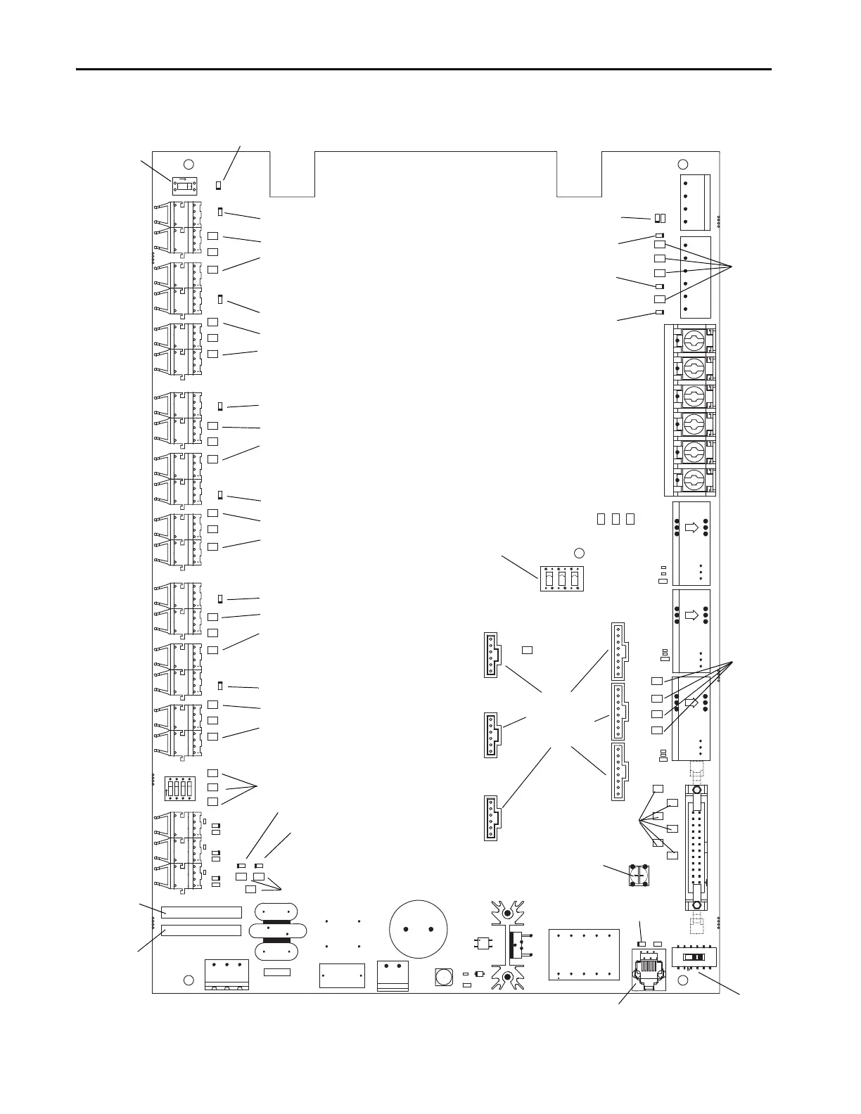
SW2: When ON
(right) provides test
pulses to gate driver
circuits.
NOTE: Must be OFF
(left) for normal
operation.
LED (Red): ON when
test pulses on
SMC-50 Control Module
Ribbon connectors to
connect to SMC-50
control module
(underneath control
module)
LED (Green) is ON when Option
Stop Input Circuitry is Functioning
TB6: Option
Stop Current
Input and
Relay Status
Output
SW1: Selects CT
Current Input. NOTE:
Must be on (up) for
Normal Operation.
Voltage
Feedback
Test Points
TB5: Current Transformer Connections
Module Common:
DO NOT CONNECT
to this terminal
LED (Green): ON when signal present at
temperature feedback fibre optic receivers
LED (Yellow): ON when
Phase A+ gate signal active
Phase A
Fiber Optic Transmitters send gate signals to driver boards
Phase B
Fibre Optic Transmitters
Phase C
Fibre Optic Transmitters
Tem pe rat ure
Feedback
Fibre Optic
Receivers
L N G
Control Power
110…240V AC
L N
Power out to
SMC-50
SW3: detects
temperature
feedback
channels
Phase A+ gate signal
Common for Gate/Pulse
Test Points
LED (Yellow): ON when
Phase A- gate signal active
Phase A- gate signal
Common for Gate/Pulse
Test Points
LED (Yellow): ON when
Phase B+ gate signal active
Phase B+ gate signal
Common for Gate/Pulse
Test Points
LED (Yellow): ON when
Phase B- gate signal active
Phase B- gate signal
Common for Gate/Pulse
Test Points
LED (Yellow): ON when
Phase C+ gate signal active
Phase C+ gate signal
Common for Gate/Pulse
Test Points
LED (Yellow): ON when
Phase C+ gate signal active
Phase C+ gate signal
Common for Gate/Pulse
Test Points
LED (Green): ON when +15V rail is present
LED (Green): ON when +5V rail is present
Power Supply Test Points
Programming
Interface
SW4 Firmware
Programming
Switch
Ribbon Connector to Voltage Sensing Board
LED (Red) is ON when
in program mode
Current
Feedback
Tes t
Points
LED (Green) is ON when
+12V Rail is present
LED (Green) is ON when
-12V Rail is present
LED (Green) is ON when
15V_IN Rail is present
Power
Supply
Tes t
Points
Replacement
Part Number
Serial
Number

 Loading...


