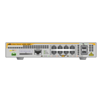
To configure OSPF host routes, click the OSPF Host Route Settings link.To add a new OSPF Route, click the Add button. Configure the setting in the
menu that appears.The
Add and Modify menus for OSPF host route setting are nearly identical.The difference being that if you are changing an existing
configuration you will be unable to change the Host Address.To change an existing configuration, click on the hyperlinked Host Address in the list for the
configuration you want to change and proceed to change the metric or area ID.To eliminate an existing configuration, click the
8 in the Delete column for the
configuration being removed.
Figure 6- 120. OSPF Host Route Settings window
Use the menu below to set up OSPF host routes.
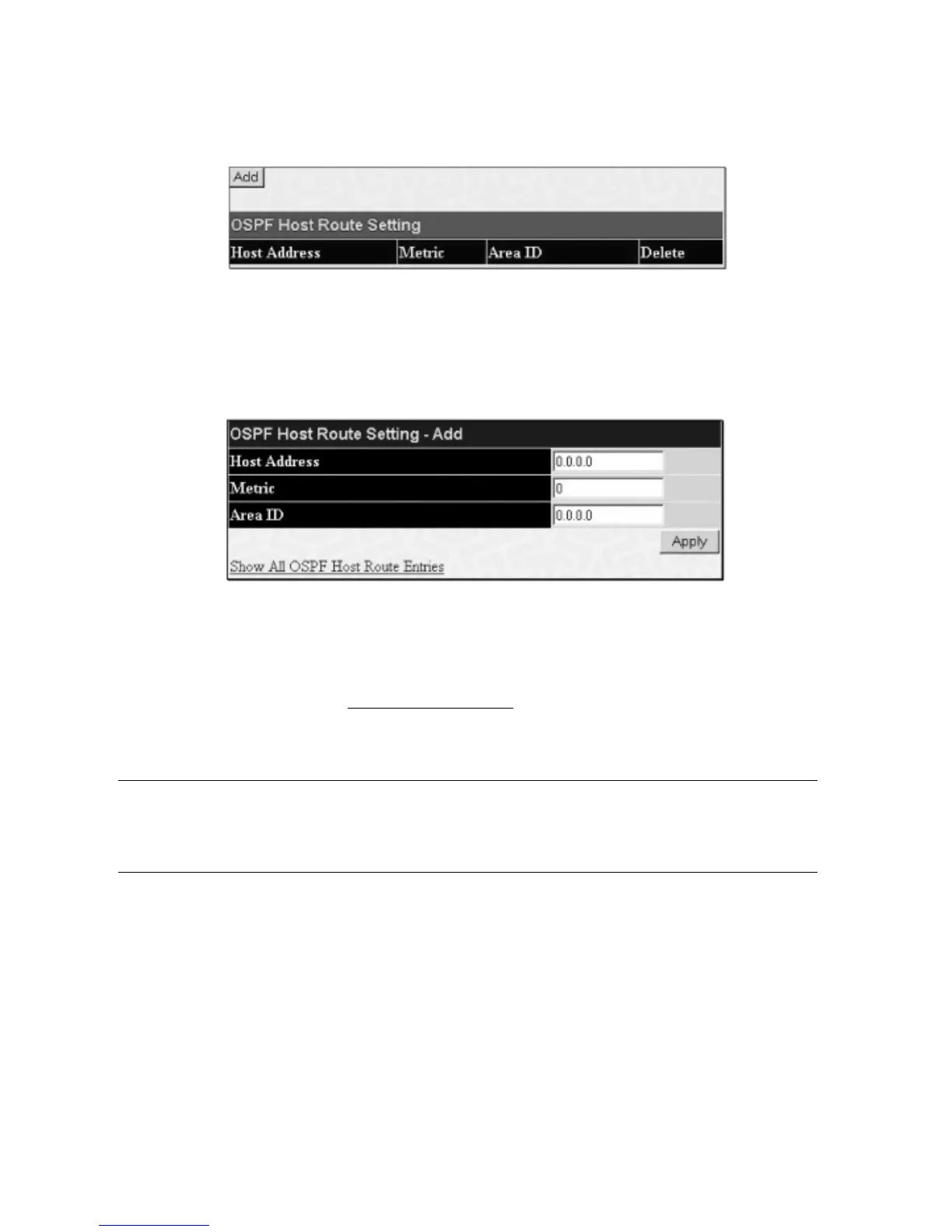
Figure 6- 121. OSPF Host Route Setting – Add window
Specify the host route settings and click the
Apply button to add or change the settings.The new settings will appear listed in the OSPF Host Route
Settings
list.
To view the previous window, click the Sho
w All OSPF Host Route Entries link to return to the previous window.
The following fields are configured for OSPF host route:
Parameter Description
Host Address The IP address of the OSPF host.
Metric A value between 1 and 65535 that will be advertised for the route.
Ar
ea ID
A 32-bit n
umber in the f
orm of an IP ad
dr
ess (xxx.xxx.xxx.xxx) that uniquel
y identifies the OSPF ar
ea in the
OSPF domain.
DHCP / BOOTP Relay
The BOOTP hops count limit allows the maximum number of hops (routers) that the BOOTP messages can be relayed through to be set. If a packet’s hop count
is mor
e than the hop count limit,
the pack
et is dropped.The range is between
1 and 16 hops,
with a default value of
4.
The r
ela
y time threshold sets the minimum
time (in seconds) that the Switch will wait before forwarding a BOOT REQUEST packet. If the value in the seconds field of the packet is less than the relay time
threshold, the packet will be dropped.The range is between
0 and 65,536 seconds, with a default value of 0 seconds.
DHCP / BOOTP Relay Information
T
o enable and configur
e BOO
TP or DHCP on the Switch,
click
Configur
ation > DHCP/BOO
TP R
elay > DHCP/BOO
TP Gl
obal Settings
:
122
Allied Telesyn AT-9724TS High-Density Layer 3 Stackable Gigabit Ethernet Switch

 Loading...