6-2 IP Address
The IP Address may initially be set using the console interface prior to connecting to it through the Ethernet. If the Switch IP address has not yet been changed,
read the introduction of the AT-9724TS Command Line Interface Reference Manual or return to Chapter 4 of this manual for more information.
To change IP settings using the web manager you must access the IP Address menu located in the Configuration folder.
To configure the Switch's IP address:
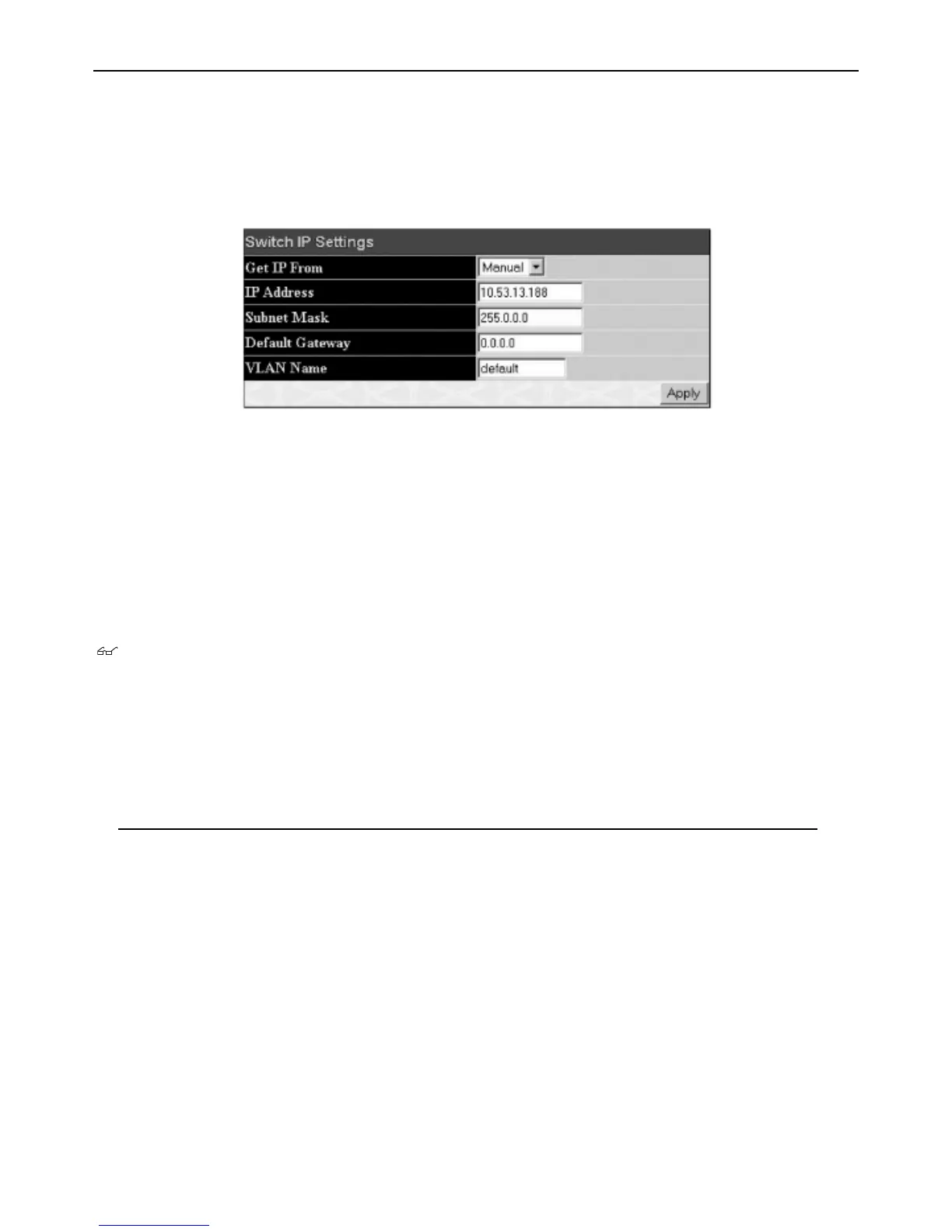
Open the Configuration folder and click the IP Address menu link.The web manager will display the Switch's current IP settings in the IP configuration
menu, as seen below.
Figure 6- 2. IP Address Settings window
To manually assign the Switch's IP address, subnet mask, and default gateway address:
1. Select
Manual from the Get IP From drop-down menu.
2. Enter the appropriate
IP Address and Subnet Mask.
3. If you want to access the Switch from a different subnet from the one it is installed on, enter the IP address of the
Default Gateway. If you will
manage the Switch from the subnet on which it is installed, you can leave the default address (0.0.0.0) in this field.
4. If no VLANs have been previously configured on the Switch, you can use the default VLAN Name.The default VLAN contains all of the Switch ports
as members. If VLANs have been previously configured on the Switch, you will need to enter the
VLAN ID of the VLAN that contains the port
connected to the management station that will access the Switch.The Switch will allow management access from stations with the same VID listed
here.
Note: The Switch's factory default IP address is 10.0.0.1 with a subnet mask of 255.0.0.0 and a default gateway of 0.0.0.0.
To use the BOOTP or DHCP protocols to assign the Switch an IP address, subnet mask, and default gateway address:
Use the
Get IP From:<Manual> pull-down menu to choose from BOOTP or DHCP.This selects how the Switch will be assigned an IP address on the next
r
eboot.
The IP Address Settings options are:
Parameter Description
BOOTP
The Switch will send out a BOOTP broadcast request when it is powered up.The BOOTP protocol allows IP
ad
dr
esses, network masks, and default gateways to be assigned by a central BOOTP server. If this option is set,
the Switch will first look for a BOOTP server to provide it with this information before using the default or
previously entered settings.
DHCP The Switch will send out a DHCP br
oadcast r
equest when it is po
w
er
ed up
.
The DHCP pr
otocol allows IP
addresses, network masks, and default gateways to be assigned by a DHCP server. If this option is set, the
Switch will first look f
or a DHCP ser
v
er to pr
o
vide it with this inf
ormation before using the default or
previously entered settings.
Manual Allows the entry of an IP address, Subnet Mask, and a Default Gateway for the Switch.These fields should be of
the form xxx.xxx.xxx.xxx, where each xxx is a number (represented in decimal form) between 0 and 255.This
ad
dr
ess should be a unique ad
dr
ess on the netw
ork assigned f
or use by the network administrator.
Subnet Mask A Bitmask that determines the extent of the subnet that the Switch is on.
Should be of the f
orm
xxx.xxx.xxx.xxx,
wher
e each
xxx is a n
umber (r
epresented in decimal) between 0 and 255.The value
should be 255.0.0.0 for a Class A network, 255.255.0.0 for a Class B network, and 255.255.255.0 for a Class C
netw
ork,
but custom subnet masks are allowed.
Default Gateway IP ad
dress that determines where packets with a destination address outside the current subnet should be
sent.
This is usuall
y the ad
dr
ess of a r
outer or a host acting as an IP gate
wa
y
.
If y
our network is not part of an
intranet, or you do not want the Switch to be accessible outside your local network, you can leave this field
unchanged.
29
Allied Telesyn AT-9724TS High-Density Layer 3 Stackable Gigabit Ethernet Switch

 Loading...