Chapter 2 - Installation
2-1 Package Contents
2-2 Before You Connect to the Network
2-3 Installing the Switch Without the Rack
2-4 Rack Installation
2-5 Power On
2-6 Power Failure
2-7 Redundant Power System
2-1 Package Contents
Open the shipping carton of the Switch and carefully unpack its contents.The carton should contain the following items:
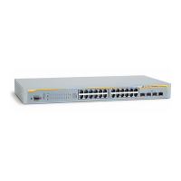
• One AT-9724TS Switch
• One AC power cord
• One Stacking Cable
• One CD which includes the AT-9724TS Manual, and Net.Cover documents
• One Warranty Card
• Mounting kit (two brackets and screws)
•
Four rubber feet with adhesive backing
• RS-232 console cable
• If any item is found missing or damaged, please contact your local Allied Telesyn Reseller for replacement.
2-2 Before You Connect to the Network
The site where you install the Switch may greatly affect its performance. Please follow these guidelines for setting up the Switch.
• Install the Switch on a sturdy, level surface that can support at least 6.6lb. (3kg) of weight. Do not place heavy objects on the Switch.
• The power outlet should be within 1.82 metres (6 feet) of the Switch.
• Visually inspect the power cord and see that it is fully secured to the AC power port.
• Make sure that there is proper heat dissipation from and adequate ventilation around the Switch. Leave at least 10 cm (4 inches) of space at the front
and rear of the Switch for ventilation.
• Install the Switch in a fairly cool and dry place for the acceptable temperature and humidity operating ranges.
• Install the Switch in a site free from strong electromagnetic field generators (such as motors), vibration, dust, and direct exposure to sunlight.
• When installing the Switch on a level surface, attach the rubber feet to the bottom of the device.The rubber feet cushion the Switch, protect the
casing from scratches and prevent it from scratching other surfaces.
• Ensure you program the Switch with a valid IP address – see section xxxx.
2-3 Installing the Switch without a Rack
When installing the Switch on a desktop or shelf, the rubber feet included with the Switch should first be attached. Attach these cushioning feet on the bottom
at each corner of the device. Allow enough ventilation space between the Switch and any other objects in the vicinity.
14
Allied Telesyn AT-9724TS High-Density Layer 3 Stackable Gigabit Ethernet Switch
 Loading...