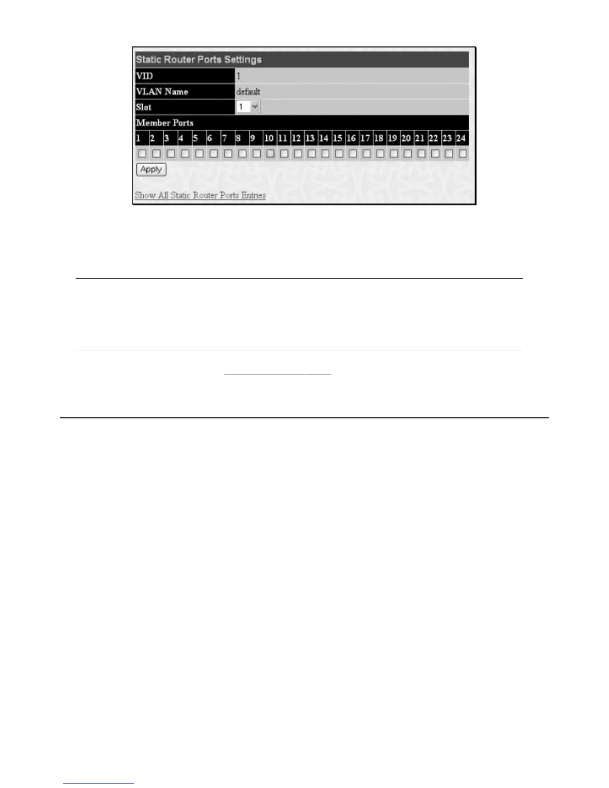
Figure 6- 20. Static Router Ports Settings window
The following parameters can be set:
Parameter Description
VID (VLAN ID) This is the VLAN ID that, along with the VLAN Name, identifies the VLAN where the multicast router is
attached.
VLAN Name This is the name of the VLAN where the multicast router is attached.
Unit Choose the Switch ID number of the Switch in the switch stack to be modified.
Member Ports These are the ports on the Switch that will have a multicast router attached to them.
Click
Apply to implement the new settings, click the Show All Static Router Port Entries link to return to the Current Static Router Port Entries
window.
6.11 Spanning Tree
This Switch supports three versions of the Spanning Tree Protocol; 802.1d STP, 802.1w Rapid STP and 802.1s MSTP. 802.1d STP will be familiar to most
networking professionals. However, since 802.1w RSTP and 802.1s MSTP has been recently introduced to Allied Telesyn managed Ethernet switches, a brief
introduction to the technology is provided below followed by a description of how to set up 802.1d STP, 802.1w RSTP and 802.1s MSTP.
802.1s MSTP
Multiple Spanning Tree Protocol, or MSTP, is a standard defined by the IEEE community that allows multiple VLANs to be mapped to a single spanning tree
instance
,
which will pr
o
vide m
ultiple pathways across the network.Therefore, these MSTP configurations will balance the traffic load, preventing wide scale
disruptions when a single spanning tree instance fails.This will allow for faster convergences of new topologies for the failed instance. Frames designated for these
VLANs will be processed quickly and completely throughout interconnected bridges utilizing either of the three spanning tree protocols (STP, RSTP or MSTP).
This protocol will also tag BDPU packets so receiving devices can distinguish spanning tree instances, spanning tree regions and the VLANs associated with them.
These instances will be classified b
y an MSTI ID. MSTP will connect multiple spanning trees with a Common and Internal Spanning Tree (CIST).The CIST will
automaticall
y determine each MSTP r
egion,
its maxim
um possible extent and will appear as one virtual bridge that runs a single spanning tree. Consequentially,
frames assigned to different VLANs will follow different data routes within administratively established regions on the network, continuing to allow simple and full
processing of frames, regardless of administrative errors in defining VLANs and their respective spanning trees.
Each switch utilizing the MSTP on a network will have a single MSTP configuration that will have the following three attributes:
1. A configuration name defined by an alphanumeric string of up to 32 characters (defined in the
MST Configuration Table window in the
Configur
ation Na
me
field).
2. A configuration revision number (named here as a
Revision Level and found in the MST Configuration Table window) and;
3.
A 4096 element table (defined her
e as a
VID List in the MST Configur
ation T
able
windo
w) which will associate each of the possible 4096
VLANs supported by the Switch for a given instance.
T
o utilize the MSTP function on the Switch,
thr
ee steps need to be tak
en:
1. The Switch must be set to the MSTP setting (found in the
STP Bridge Global Settings window in the STP Version field).
2. The correct spanning tree priority for the MSTP instance must be entered (defined here as a
Priority in the STP Instance Settings window
when configuring an
MSTI ID settings).
3. VLANs that will be shar
ed m
ust be added to the
MSTP Insta
nce ID
(defined her
e as a
VID List in the MST Configur
ation T
a
ble
windo
w
when configuring an MSTI ID settings).
42
Allied Telesyn AT-9724TS High-Density Layer 3 Stackable Gigabit Ethernet Switch

 Loading...