Chapter 3 - Connecting the Switch
• 3-1 Switch to End Node
• 3-2 Switch to Hub or Switch
• 3-3 Connecting to Network Backbone or Server
• 3-4 Stacking and the AT-9724TS
3-1 Switch To End Node
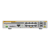
End nodes include PCs outfitted with a 10, 100 or 1000Mbps RJ45 Ethernet Network Interface Card (NIC) and most routers.
An end node can be connected to the Switch via a twisted-pair UTP/STP cable.The end node should be connected to any of the 24 1000T ports of the Switch.
Figure 3- 1. Switch connected to an end node
The Link/Act LEDs for each UTP port will light green or amber when the link is valid.A blinking LED indicates packet activity on that port.
3-2 Switch to Hub or Switch
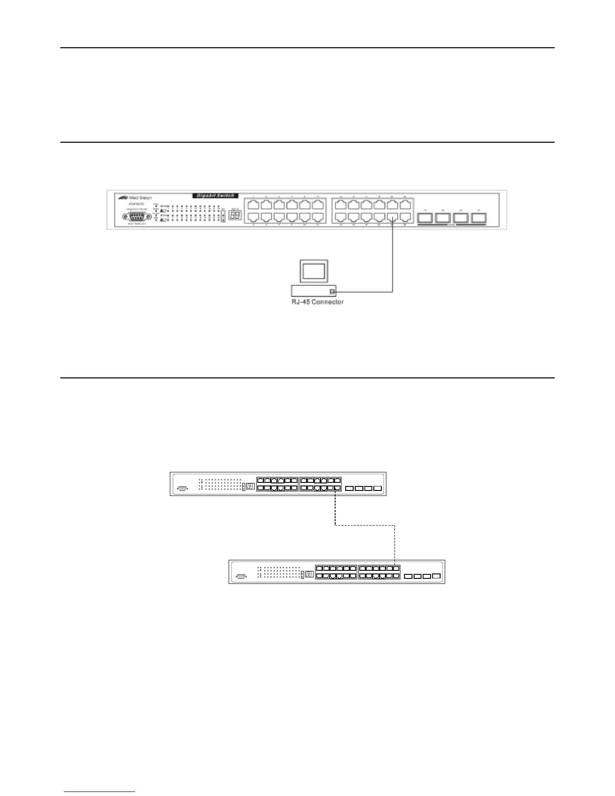
These connections can be accomplished in a number of ways using a normal cable.
• A 10T hub or switch can be connected to the Switch via a twisted-pair Category 3, 4 or 5 UTP/STP cable.
• A 100TX hub or switch can be connected to the Switch via a twisted-pair Category 5 UTP/STP cable.
• A 1000T switch can be connected to the Switch via a twisted pair Category 5e UTP/STP cable.
• A switch supporting a fibre-optic uplink can be connected to the Switch’s SFP ports via fibre-optic cabling.
Figure 3- 2. Switch connected to a port on a hub or switch using either a straight or crossover cable – any normal cable is fine
17
Allied Telesyn AT-9724TS High-Density Layer 3 Stackable Gigabit Ethernet Switch
13 5 7
9
11
13 15
2
4 6 8 10 12 14
16
17
19 21
23
18
20
22
24
21 22
23
24
2 4 6 8 10 12 14 16 18 20 22 24
1 3 5 7 9 11 13 15 17 19 21 23
Power
Mas
ter
Con
sole
RPS
1000
Link
Act
1000
Link
Act
1
2
SIO
Stack ID
AT- 9724TS
1
35 7
9
11
13 15
2
4
6 8 10 12 14
16
17
19 21
23
18
20
22
24
21 22
23
24
2
4 6 8 10 12 14 16 18 20 22 24
1
3 5 7 9 11 13 15 17 19 21 23
Pow
er
Mas
ter
Console
RPS
1000
Link
Act
1000
Link
Act
1
2
SIO
Stack ID
AT-
9724TS
UTP cable

 Loading...