• SNMP support
• Secure Sockets Layer (SSL) and Secure Shell (SSH) support
• Port Mirroring support
• MIB support for:
RFC1213 MIB II
RFC1493 Bridge
RFC1757 RMON
RFC1643 Ether-like MIB
RFC2233 Interface MIB
IF MIB
Private MIB
RFC2674 for 802.1p
IEEE 802.1x MIB
• RS-232 DCE console port for Switch management
• Provides parallel LED display for port status such as link/act, speed, etc.
1-4 Ports
Twenty-four (24) 1000T combo ports that may be used in uplinking various network devices to the Switch, including PCs, hubs and other switches to provide a
gigabit Ethernet uplink in full-duplex mode.
Four (4) high-performance SFP ports for a fibre-optic connection to various network connections, for use over great distances.
Two 10-gigabit stacking ports at the rear of the Switch for stacking switches utilizing ring topology.
RS-232 DCE Diagnostic port (console port) for setting up and managing the Switch via a connection to a console terminal or PC using a terminal emulation
program.
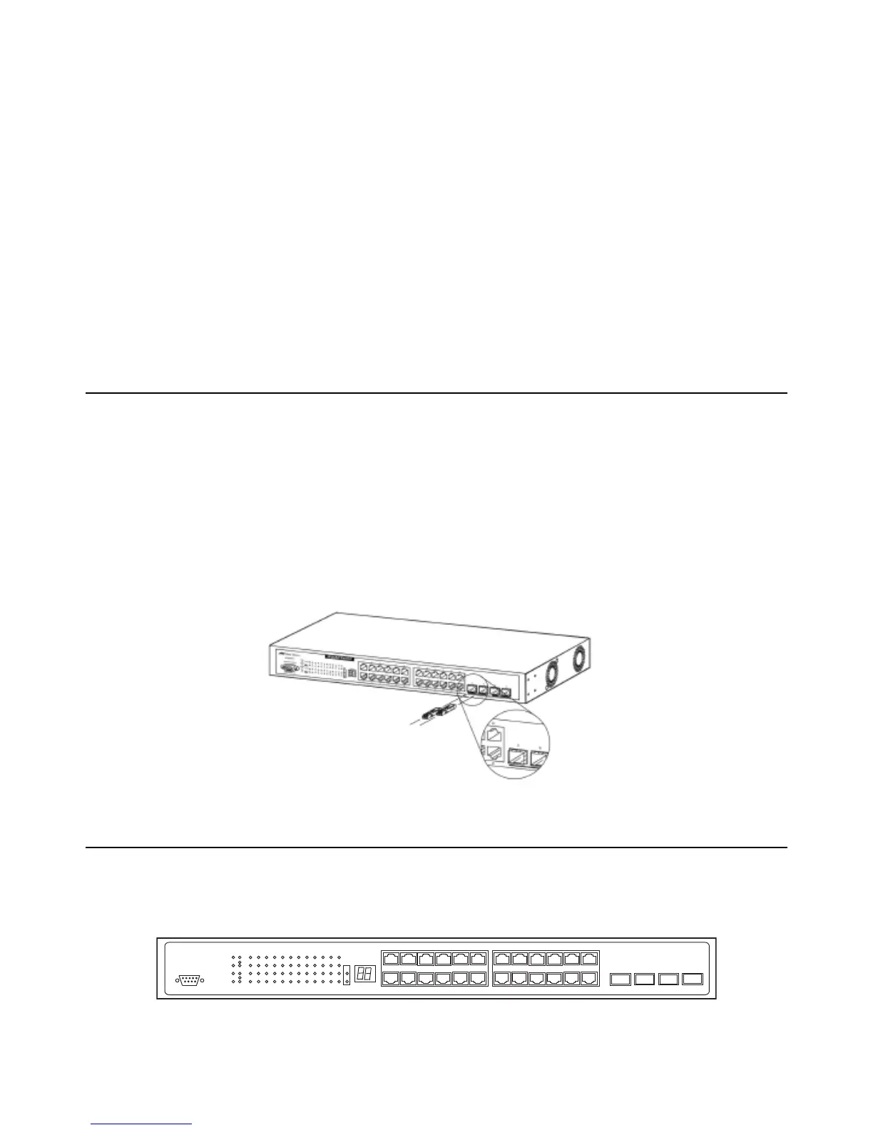
Installing the SFP ports
The Switch is equipped with four SFP (Small Form Factor Portable) ports, which are to be used with fibre-optical transceiver cabling in order to uplink various
other networking devices for a gigabit link that may span great distances.
Figure 1- 1. Inserting the fibre-optic transceivers into the AT-9724TS
1-5 Front Panel Components
The fr
ont panel of the Switch consists of LED indicators f
or P
o
w
er
,
Master
, Console, RPS, SIO (stacking), a seven-segment Stack ID LED and for Link/Act for each
port on the Switch, as well as 24 1000T ports, 4 SFP gigabit Ethernet ports and a RS-232 DCE console port for Switch management.
Figure 1- 2. Front Panel View of the AT-9724TS as shipped
Comprehensive LED indicators display the status of the Switch and the network.
12
Allied Telesyn AT-9724TS High-Density Layer 3 Stackable Gigabit Ethernet Switch

 Loading...