IGMP Snooping
Internet Group Management Protocol (IGMP) snooping allows the Switch to recognize IGMP queries and reports sent between network stations or
devices and an IGMP host.When enabled for IGMP snooping, the Switch can open or close a port to a specific device based on IGMP messages passing through
the Switch.
In order to use IGMP Snooping it must first be enabled for the entire Switch (see
Advanced Settings).You may then fine-tune the settings for each VLAN
using the
IGMP Snooping link in the Configuration folder. When enabled for IGMP snooping, the Switch can open or close a port to a specific Multicast
group member based on IGMP messages sent from the device to the IGMP host or vice versa.The Switch monitors IGMP messages and discontinues forwarding
multicast packets when there are no longer hosts requesting that they continue. Use the
IGMP Snooping Group Entry Table to view IGMP Snooping
status.To modify settings, click the
Modify button for the VLAN Name entry you want to change.
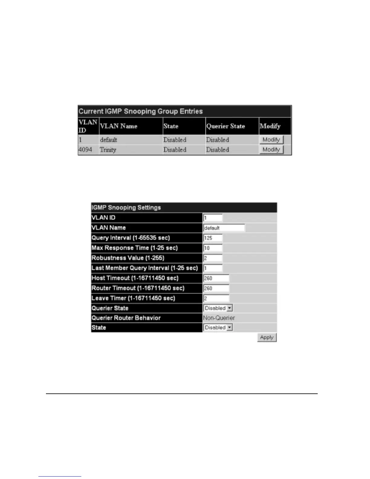
Use the Current IGMP Snooping Group Entries window to view IGMP Snooping settings.To modify settings, click the Modify button for the VLAN
ID you want to change.
Figure 6- 17. Current IGMP Snooping Group Entries
Clicking the
Modify button will open the IGMP Snooping Settings menu, shown below:
Figure 6- 18. IGMP Snooping Settings window
The f
ollowing parameters may be viewed or modified:
Parameter Description
VLAN ID This is the VLAN ID that, along with the VLAN Name, identifies the VLAN the user wishes to modify the
IGMP Snooping Settings for.
VLAN Name This is the VLAN Name that, along with the VLAN ID, identifies the VLAN the user wishes to modify the
IGMP Snooping Settings for.
Query Interval The Query Interval field is used to set the time (in seconds) between transmitting IGMP queries. Entries
betw
een 1 and 65535 seconds ar
e allo
w
ed.
Default = 125.
Max Response Time This determines the maximum amount of time in seconds allowed before sending an IGMP response report.
The
Max R
esponse T
ime
field allo
ws an entr
y between 1 and 25 (seconds). Default = 10.
40
Allied Telesyn AT-9724TS High-Density Layer 3 Stackable Gigabit Ethernet Switch

 Loading...