10
We reserve the right to make technical changes.
83052300eUK © ait-deutschland GmbH
2.0
InstallatIon of the Wall control luxtronIk 2.0
ATTENTION
The following instructions apply to the Luxtronik
2.0 wall-mounted controller only. Therefore, before
each further step, check which version of the wall
controller you have.
If you have the Luxtronik 2.1 version, ignore this
section and go to the section “Installing the Lux-
tronik 2.1 wall-mounted controller” starting on
page 12.
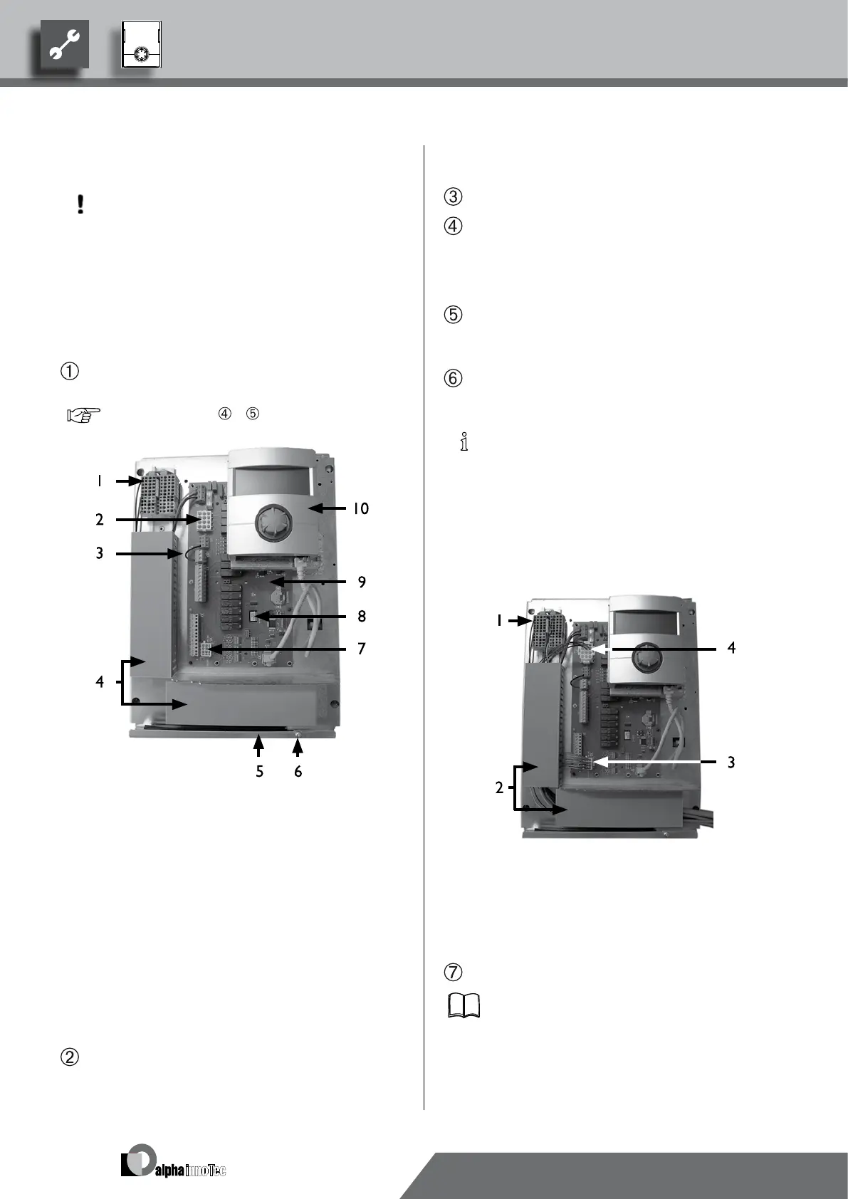
If not yet carried out: Remove housing cover of the
heating and heat pump control…
page 9, Instruction –
1 Terminal block for 230 V voltage supply
2 Connection for 230 V control line to the heat
pump (socket X1)
3 Electricity supply utility bridge (must be removed
when connecting a oating contact)
4 Cable ducts with covers
5 Cable entry with folding bracket
6 Fastening screw of the folding bracket
7 Connection for sensor line to the heat pump
(socket X5)
8 Slot for optional extension card “Comfort”
9 Control card of the heating and heat pump con-
trol
10 Operating element
Loosen fastening screw of the folding bracket for the
cable entry and pull the folding bracket downwards
until it is possible to fold away upwards. Fold folding
bracket upwards and away to the side…
Remove covers from the cable ducts…
Insert plug of the 230 V control line leading to the heat
pump into socket X1.
Then route the control line downwards through the
cable ducts and outwards through the cable entry…
Insert plug of the sensor line into socket X5. Route
the sensor line downwards through the cable ducts and
outwards through the cable entry…
Connect the 230 V voltage supply line to the voltage
supply terminal block…
NOTICE
Internal fuse 6.3AT.
The terminal block has spring-type terminals to
maximum 2.5 mm
2
.
Insulate the cable jacket so that the jacket end is lo-
cated between the sealing lip and cable duct.
Basic wiring:
1 Connected 230 V voltage supply
2 Line wiring in the cable ducts
3 Connected sensor line to the heat pump
4 Connected 230 V control line to the heat pump
If necessary, install additional external cables…
Instruction manual for your appliance, “Connection
layout” and “Circuit diagrams” for your appliance
type