35
We reserve the right to make technical changes.
83052300eUK © ait-deutschland GmbH
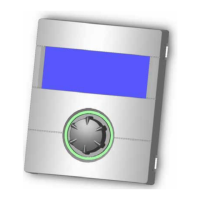
query Inputs
In the “Service Information” menu select the menu
eld “Inputs”…
The screen changes to the menu “Service Information
inputs”…
NOTICE
This menu shows whether the digital inputs of the
controller are switched on or off.
Defr/Brin/Flow Defrost, Brine pressure, ow
Depending on the device type, the input can full vari-
ous functions:
For L/W-devices Defrost end pressostat:
On = Defrost is terminated.
For LWD, S/W and W/W devices with ow switch con-
nected at the factory:
On = Flow okay.
For S/W devices without ow switch connected at the
factory, a brine pressostat can be connected:
On = brine pressure sufcient.
SW-therm. switch Domestic hot water thermostat
On = Domestic hot water requirement
Electr. suppl. Off-time of the electrical supply
Off = Off-time
High pressure High-pressure pressostat
Off = Pressure okay
Motor protect. Motor protection
On = Motor protection okay.
Low pressure Low pressure pressostat
On = Pressure okay.
PEX Connection of an external current
anode
(possible for some devices)
Return to menu “Service Information”.
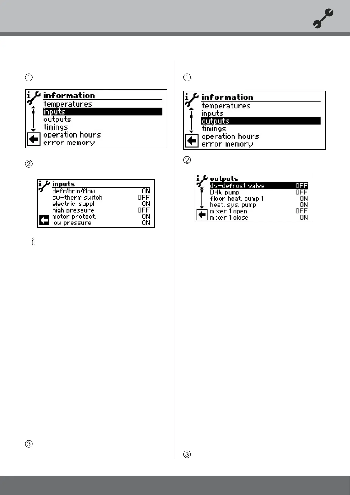
query outputs
In the “Service Information” menu select the menu
eld “Outputs”…
The screen changes to the menu “Service information
Outputs”…
CV-Defrost. valve Valve / Circuit reversal
ON = Thaw mode or rather cycle
reversal becomes active
DHW pump Domestic hot water circulation
pump
Floor heat. pump 1 Floor heating circulation pump
Heat. sys. pump Heating circulation pump
Mixer 1 Open Mixer 1 opens
On = opens / Off = no control
Mixer 1 Close Mixer 1 Close
On = closes / Off = no control
Ventilation Ventilation of the heat pump hous-
ing for certain L/W devices.
For L/W size types (coding “L2G”),
second stage of the ventilator
Fan-heats. pump Ventilator, well or brine circulation
pump
Compressor 1 Compressor 1 in heat pump
Compressor 2 Compressor 2 in heat pump
CP Circulation pump
Suppl. pump Additional circulating pump
2nd heat gen. 1 Second heat generator 1
2nd heat gen. 2 Second heat generator 2–
Collective fault (function collective
fault: Continuous ON in the event
of a fault, cycles 1x per second
with automatic RESET enabled)
Control signal UWP Circulation pump output in %
RPM Ventilator Current speed of the heat pump’s fan
RPM Compressor Current speed of the heat pump’
compressor
Return to menu “Service Information”.