14
We reserve the right to make technical changes.
83052300eUK © ait-deutschland GmbH
Control unit variants
Depending on the heat pump type, the control unit inte-
grated in the heating and heat pump controller is equipped
with the following interfaces:
type 1
N Network
S Connection to the control board
type 2
N Network
L LIN-BUS
S Connection to the control board
type 3
R RS485 for connecting the
room control unit (RBE)
N Network
L LIN-BUS to the control board
S not assigned
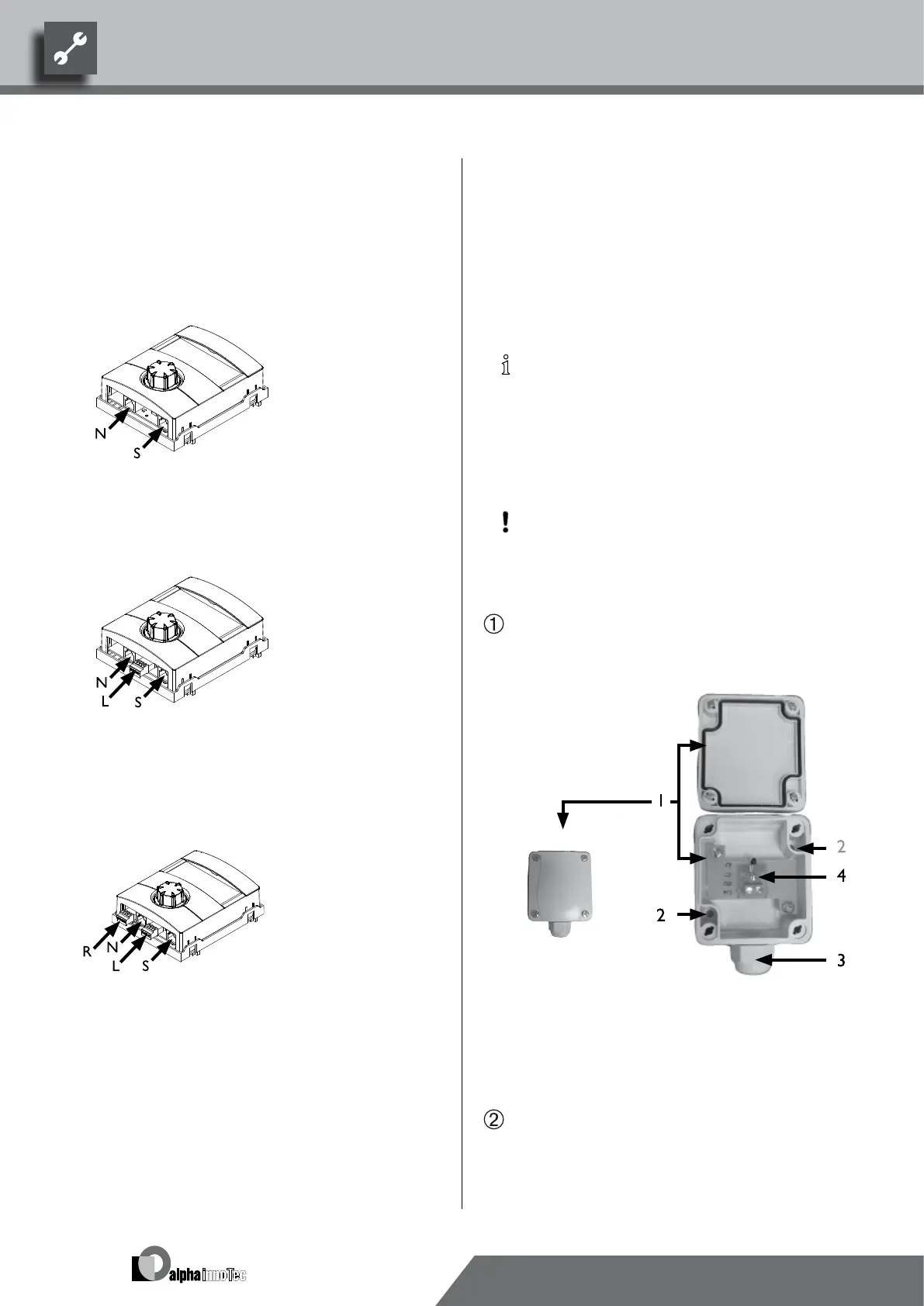
Assembly and Installation of
Sensors
external sensor
The external sensor is a function-critical accessory and in-
cluded in the scope of supply.
NOTICE
If the external sensor is not installed or defective,
the heating and heat pump regulator automatically
sets the external temperature to -5 °C. The status
display of the operating element lights up red, the
screen of the operating element reports a fault.
ATTENTION
Mount the external sensor on the north or north-
east side of buildings. The sensor must not be ex-
posed to direct sunlight.
Open the housing of the external sensor and align ≥ 2
m over the base of the fastening point. The cable
gland must point to the base…
1 External sensor housing
2 Fastening holes
3 Cable gland
4 External sensor
Pencil on fastening holes and drill, insert dowels and
screw housing of the external sensor onto the wall…