12
We reserve the right to make technical changes.
83052300eUK © ait-deutschland GmbH
2.1
InstallatIon of the Wall control luxtronIk 2.1
ATTENTION
The following instructions apply to the Luxtronik
2.1 wall-mounted controller only. Therefore, before
each further step, check which version of the wall
controller you have.
If you have the Luxtronik 2.0 version, ignore this
section and go to the section “Installing the Lux-
tronik 2.0 wall-mounted controller” starting on
page 10.
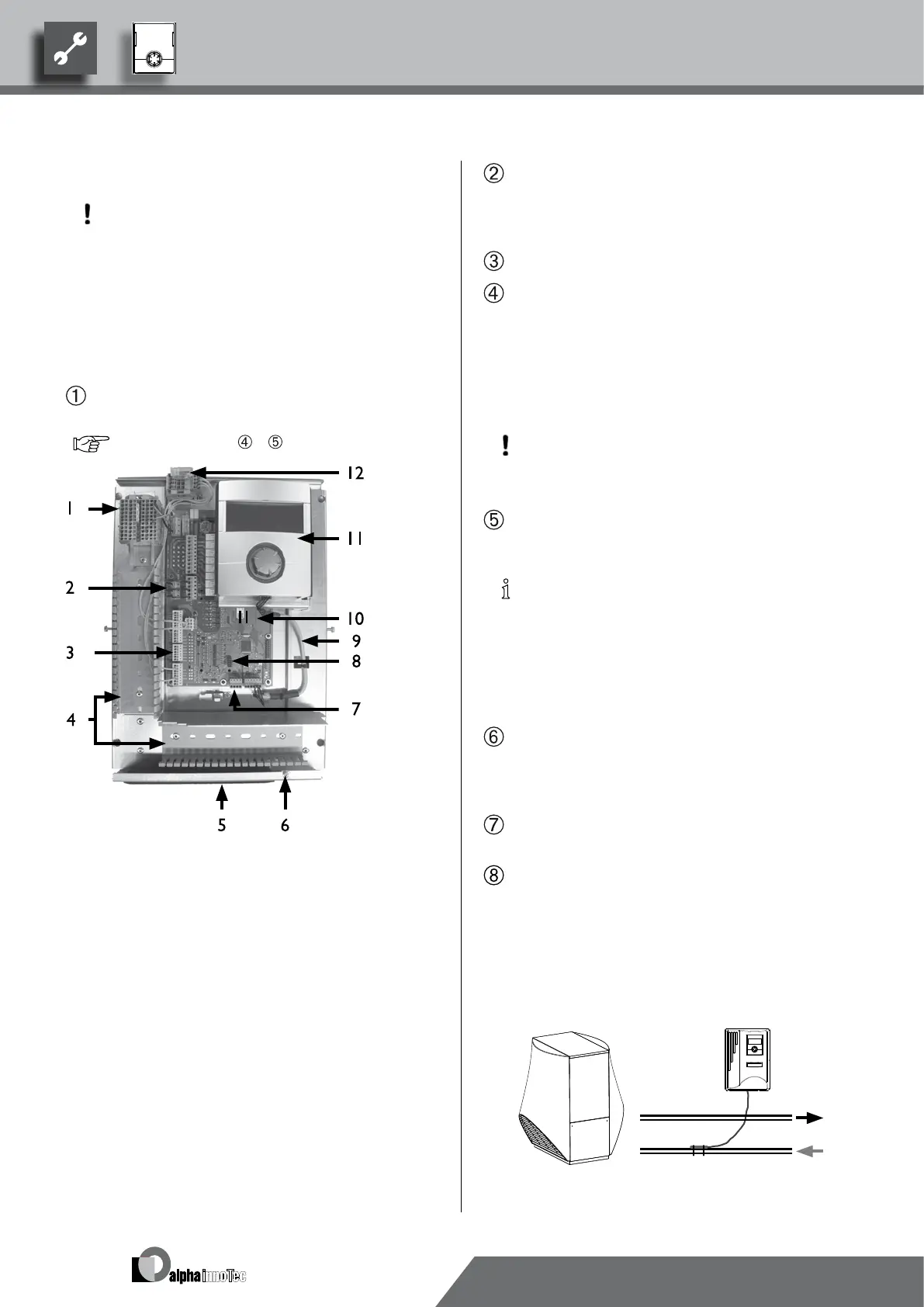
If not yet carried out: Remove housing cover of the
heating and heat pump control…
page 9, Instruction –
1 Terminal block for 1~/N/PE/230 V voltage supply
2 EVU bridges (must be removed when connecting
a oating contact)
3 TRL return sensor terminal (on NTC8)
4 Cable ducts with covers (covers now shown here
in the gure)
5 Cable entry with folding bracket
6 Fastening screw of the folding bracket
7 Terminal (X10 Modbus) for BUS cable to the
outdoor unit
8 Slot for optional “2.1-EP” circuit board
9 LIN-BUS communication cable between control
board and control unit (wired in the factory)
10 Control card of the heating and heat pump con-
trol LUX 2.1
11 Operating element
12 Connection for circulation pump PWM control
signal
Loosen fastening screw of the folding bracket for the
cable entry and pull the folding bracket downwards
until it is possible to fold away upwards. Fold folding
bracket upwards and away to the side…
Remove covers from the cable ducts…
Connect the BUS communication cable, which leads
to the heat pump, to terminal X10 of the controller
board…
Then route the BUS communication cable downwards
and through the cable ducts and through the cable
entry to the outside…
ACHTUNG
The BUS communication cable and power cables
must be laid with a spacing > 10 cm between them.
Connect the 230 V voltage supply line to the voltage
supply terminal block…
NOTICE
Internal fuse 6.3AT.
The terminal block has spring-type terminals to
maximum 2.5 mm
2
.
Insulate the cable jacket so that the jacket end is lo-
cated between the sealing lip and cable duct.
Connect the 230V power supply for the outdoor unit
to the terminal block and route it downwards through
the cable ducts and through the cable entry to the out-
door unit outside…
Connect the PWM control signal for the circulation
pump to the terminal block --X10…
A separately packed return sensor (TRL) with appropri-
ate installation materials is enclosed with the air/water
heat pump for outdoor installation. Use cable ties and
heat transfer compound to x the return sensor to
the return (heat-conducting pipe) to the heat pump as
shown in the gure and connect (to NTC8) as shown
in the circuit diagram…