11
We reserve the right to make technical changes.
83052300eUK © ait-deutschland GmbH
2.0
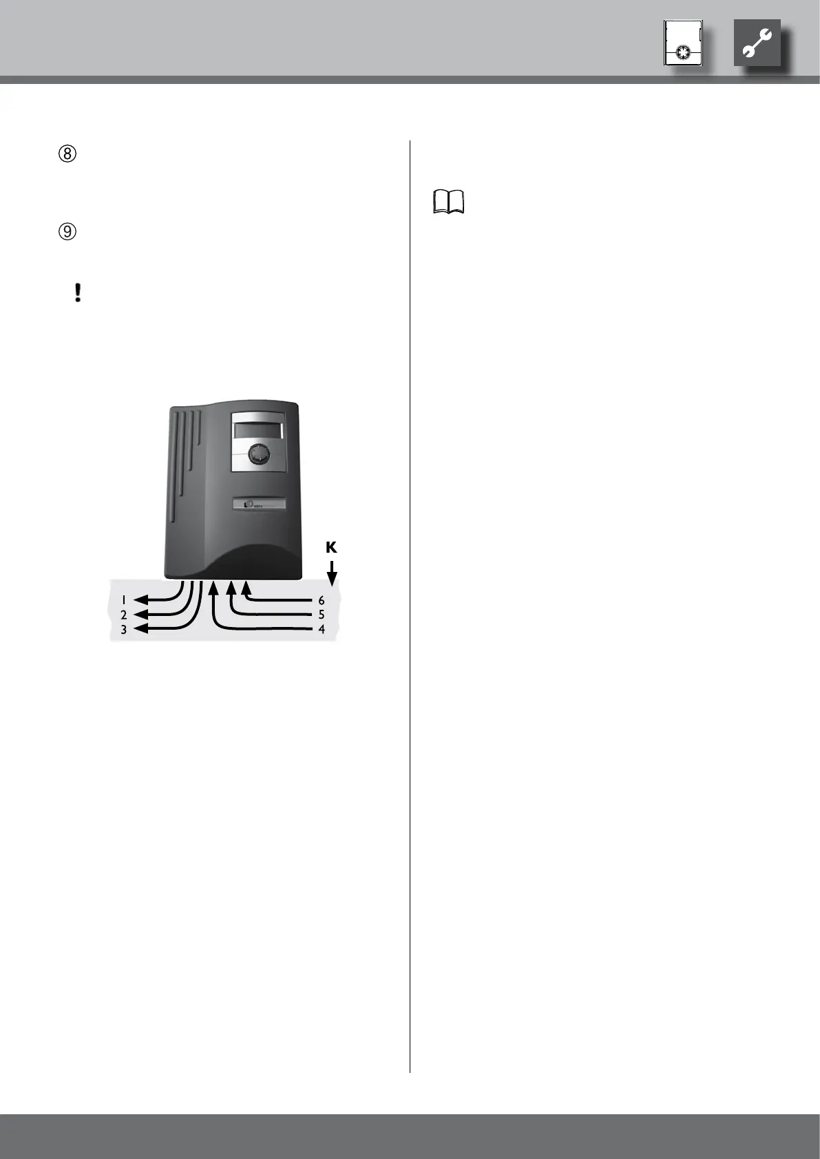
Place covers on the cable ducts. Swivel folding bracket
of the cable entry back into the initial position and
allow to latch into place below the fastening screw.
Tighten fastening screw…
Put the housing cover back on and tighten the side fas-
tening screws.
ATTENTION
Route all lines that you connect to the heating and
heat pump control outside the heating and heat
pump in a cable duct (necessary for strain relief; to
be realised at the customer).
1 230 V control line (from socket X1 to the heat
pump)
2 Sensor line (from socket X5 to the heat pump)
3 Further 230 V outputs (circulation pumps, mixers,
…)
4 Sensor lines (external)
5 Further 230 V inputs (electricity supply utility
lock, …)
6 230 V supply voltage (to the terminal block)
K Cable duct
Installation instructions for this in the operating in-
structions of your heat pump.