Series 90B ANNUNCIATOR INSTALLATION AND CONFIGURATION MANUAL
I/O Address
Each I/O Module requires an address in order for communications to the CSM
module. The Address settings are required for configuring any per point
parameters and for mapping of serial communications.
There are two versions of input modules using different methods of setting the
address. Refer to Refer to Table-1 Module Types to determine which module is
in your system.
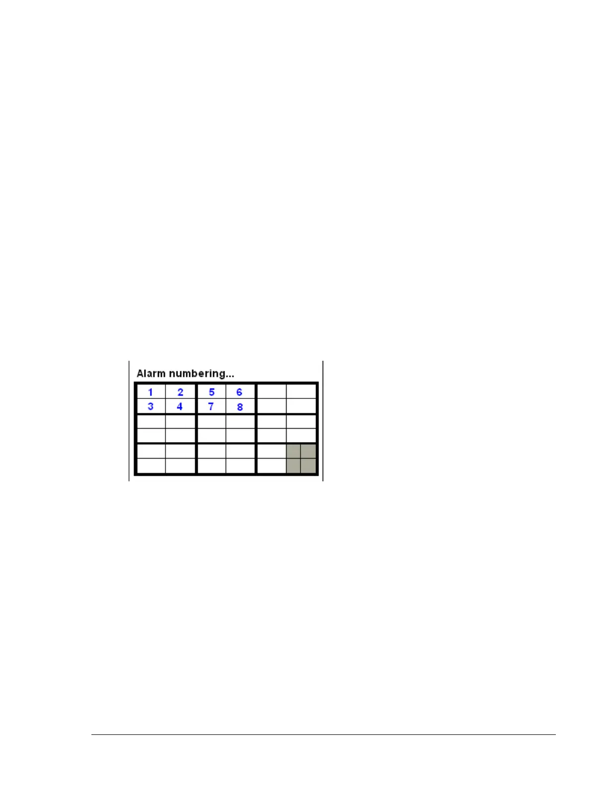
The I/O address uses a rocker switch (SW1) to indicate a binary address, starting
at 0 and incrementing by one for every module in the system, from left to right, top
to bottom. In cases where there is only one module per cell ( Window code 1E)
the binary address will increment by two. Starting at 0 in the first cell, 2 in the
second cell, 4 in the third cell etc. Zero is set when all switches are set of off.
NOTE: Care should be taken when removing and replacing I/O modules to insure
that they are replaced into the cell from which they are removed. Failure to do so
will result in out-of –sequence address.
 Loading...