14 Series 90B ANNUNCIATOR INSTALLATION AND CONFIGURATION MANUAL
Common Service Pushbutton Assemblies
The Common Service Module can be provided with Integral Pushbuttons
(Option INTB or LPPB) or no integral pushbuttons (Option NPB). In all cases,
external pushbuttons can be connected to the rear of the unit.
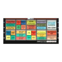
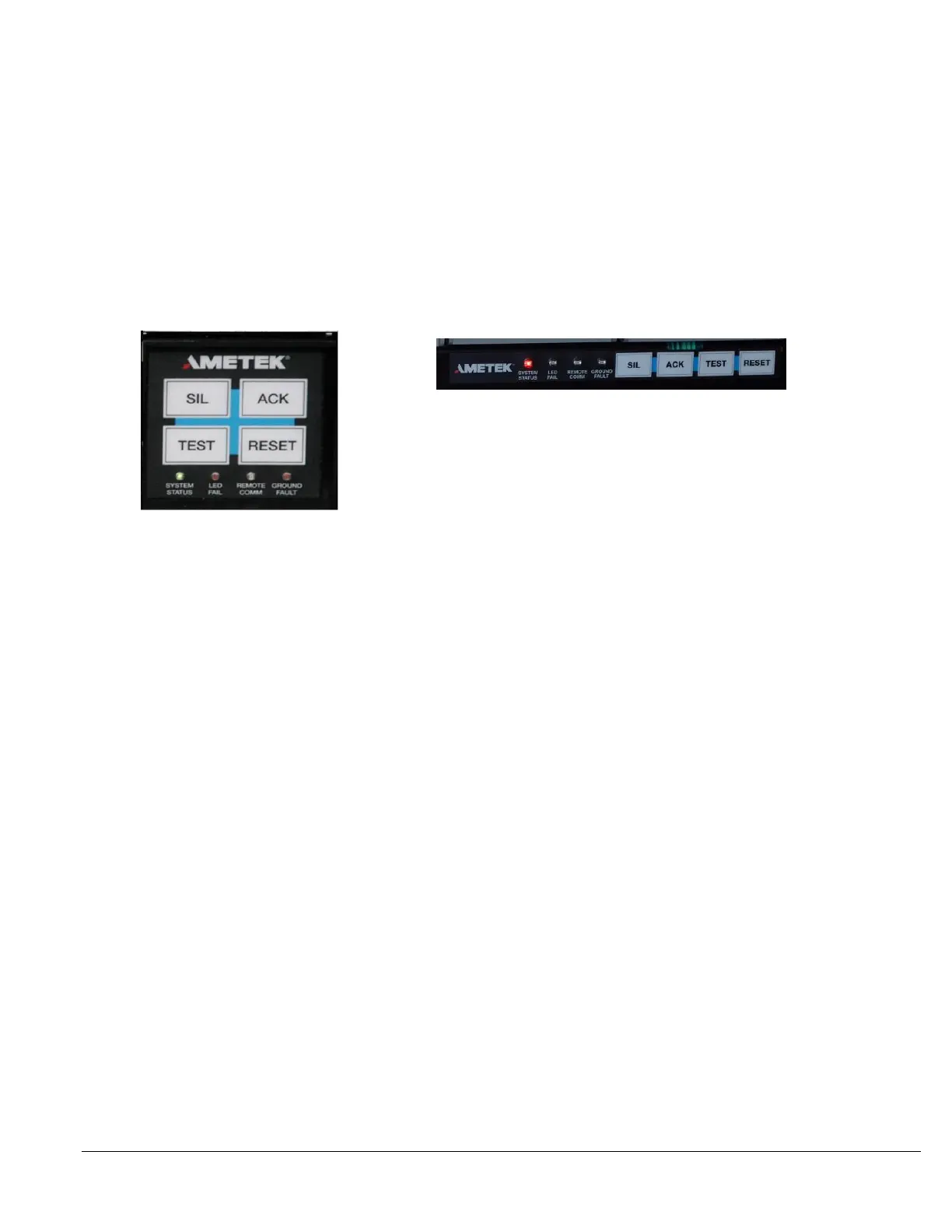
Option INTB uses pushbuttons on the lower right Common Service Cell and
Option LPPB has pushbuttons mounted on the Annunciator bezel which frees
up the lower right Common Service cell for a one or two point window.
Both options provide Silence, Acknowledge, Test and Reset Pushbuttons. Also,
The Pushbutton Assemblies include 4 diagnostic indicators.
System Status
Monitors all internal diagnostics including power. (Green is OK, Red is Fault)
LED Fail
Monitors all of the LED’s for a short or open circuit. To identify the failed
LED, press the Test Pushbuttons and see which cell has a failed LED.
Remote Comm
Flashes whenever the communications are being used via Modbus or DNP
Ground Fault
Used with the Ground Fault Option Module. Indicates the presence of a
positive or negative fault to ground in the field input wiring.
Communication Modules
The optional Communication Modules plug directly into the CSM Module
through card slot 2 and provide either a serial or Ethernet output. Only one
Communication Module per CSM is allowed.
The Serial port will be active when the ‘SPT’ option is included in the model
number code and the Ethernet port will be active when option ‘ETH’ is included in
the model number code. Systems may contain both Serial and Ethernet
communications when options ‘SPT’ and ‘ETH’ are included in the model number.
To verify which board you have, compare it to the pictures on the following pages.
 Loading...