Series 90B ANNUNCIATOR INSTALLATION AND CONFIGURATION MANUAL
INSTALLATION
MOUNTING
The system is designed for Panel Mounting and 19” Rack Mounting, Other
mounting methods such as NEMA Enclosures and Surface or Wall Mounting will
have additional details and drawings provided by the factory.
Caution must be exercised when installing this, or any other type of equipment
into racks or panels. Ensure that all equipment is properly secured using the
specified hardware in accordance with equipment manufacturer’s specifications.
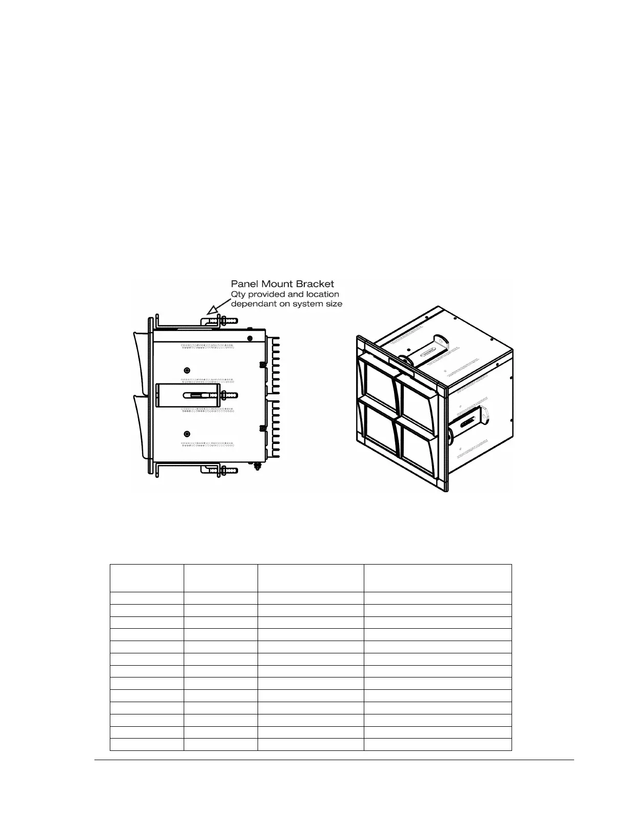
Panel Mounting(option PM, PC)
The dimensions given in the tables below refer to the size of the panel cut out
required for mounting and the front bezel height and width. The height and width
are related to the number of cells in the system. Dimensions shown are in
inches (mm).
Overall Height or
Overall Width
Panel Cut-Out Height or
Panel Cut-Out Width
Tolerance on
all cut out
dimensions is
0.0625 inches
(1.5mm)
 Loading...