EasyManuals Logo

Ametek 90B Series User Manual

Ametek 90B Series
161 pages
To Next Page IconTo Next Page
To Previous Page IconTo Previous Page
Page #35 background imageLoading...
Page #35 background image
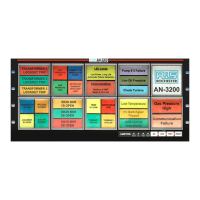
Series 90B ANNUNCIATOR INSTALLATION AND CONFIGURATION MANUAL
i. 23
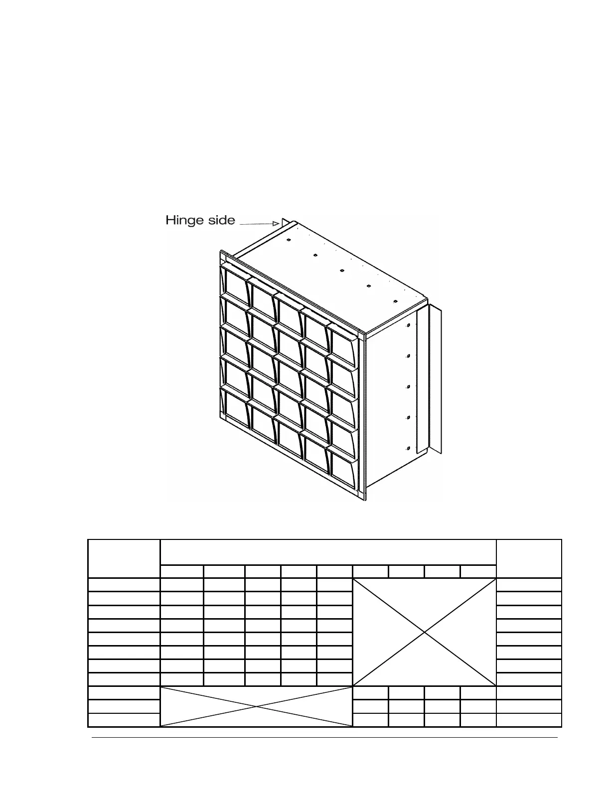
Surface (Wall) Mounting (option S)
Mounting to a wall or other surface. The annunciator is hinged on one side to
allow access to the terminal blocks in the rear of the unit. The hinge may be
moved to the right side of the annunciator by removing the brackets, rotating
them and re mounting them to the opposites side(s). Refer to table for
available sizes and dimensions. All mounting holes sized for ¼ -20 hardware.
A minimum of 10” of swing clearance is required on the hinge side of the
annunciator.
Refer to the following chart and the figures on the following page for mounting
dimensions.
Dimension
ANNUNCIATOR SIZE
Dimension
1H
2H
3H
4H
5H
2W
3W
4W
5W
A
3.65
7.12
10.59
14.06
17.53
B
4.93
8.40
11.87
15.34
18.81
C
0.40
1.12
1.12
1.12
1.12
D
1.90
4.59
4.59
4.59
4.59
E
-------
-------
8.05
8.05
8.05
F
-------
-------
-------
11.52
11.52
G
-------
-------
-------
14.99
H
2.23
5.70
9.17
12.64
16.11
8.74
12.21
15.68
19.15
J
8.39
11.86
15.33
18.80
K
10.24
13.71
17.18
20.65
L

Table of Contents

Questions and Answers:

Question and Answer IconNeed help?

Do you have a question about the Ametek 90B Series and is the answer not in the manual?

Ametek 90B Series Specifications

General IconGeneral
BrandAmetek
Model90B Series
CategorySecurity System
LanguageEnglish