Drop and insertDrop and insert
Timing SourceTiming Source
FollowsFollows
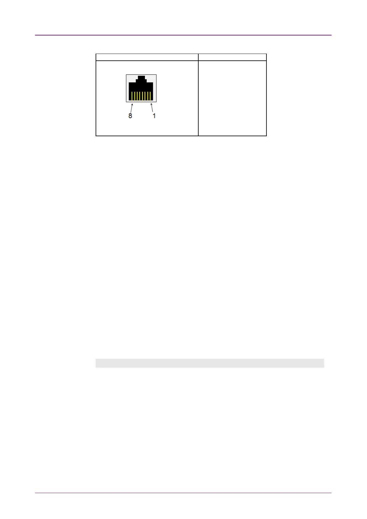
Pin assignment of E1 Balanced ConnectorsPin assignment of E1 Balanced Connectors
RJ-48 PinRJ-48 Pin SignalSignal
1 RX, Ring
2 RX, Tip
3 Ground
4 TX, Ring
5 TX, Tip
6 Ground
7 No connect
8 No connect
Be sure to confirm the cable type. For E1 cable, there are the straight cable and
the cross cable.
Select the source for the transmitter.
OnOn: transmits the received data which the data generated in the Network Master
has added.
OffOff: transmits the data generated in the Network Master.
Select the clock source.
InternalInternal: Internal clock of the module
ExternalExternal: The clock provided from the Ext Clock connector
ReceivedReceived: The clock generated from the received signal
When ExternalExternal or ReceivedReceived is set, the right hand lamp indicates whether clock
is detected or not.
55..33..11..22 E1 Signal SetupE1 Signal Setup
Touching the transmitter's E1E1 button in the navigation area will display the
screen.
To make the Port 2 transmitter follow the Port 1 transmitter (i.e. copy its
settings) when using Port 1 and Port 2, touch the drop-down menu in the
navigation area and select the Tx1Tx1. The Port 2 settings continue to follow the
Port 1 transmitter change. The default setting is NoneNone. Note that the Port 1
transmitter cannot follow the Port 2 transmitter.
Frame tabFrame tab
The FrameFrame tab contains the following parameters: