Line codeLine code
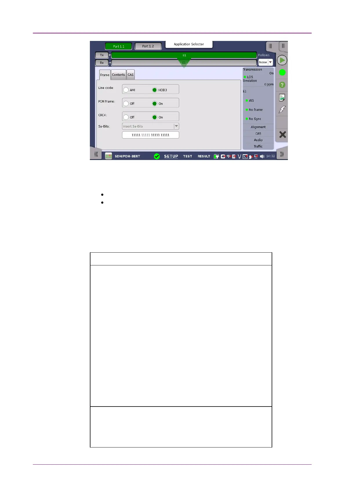
Use the Line codeLine code radio buttons to select transmission line code.
HDB3HDB3: High-Density Bipolar Order 3
AMIAMI: Alternate Mark Inversion
PCM framePCM frame
Use the PCM framePCM frame radio buttons to enable (OnOn) or disable (OffOff) insertion of
PCM frame in the transmitted signal.
PCM frame is formed by 16 E1 frames. Frame structure is shown below.
Frame Frame
numbernumber
Bits 1 to 8 of the frame (Timeslot 0)Bits 1 to 8 of the frame (Timeslot 0)
11 22 33 44 55 66 77 88
00 C1 0 0 1 1 0 1 1
11 0 1 A Sa Sa Sa Sa Sa
22 C2 0 0 1 1 0 1 1
33 0 1 A Sa Sa Sa Sa Sa
44 C3 0 0 1 1 0 1 1
55 1 1 A Sa Sa Sa Sa Sa
66 C4 0 0 1 1 0 1 1
77 0 1 A Sa Sa Sa Sa Sa
88 C1 0 0 1 1 0 1 1
99 1 1 A Sa Sa Sa Sa Sa
1010 C2 0 0 1 1 0 1 1
1111 1 1 A Sa Sa Sa Sa Sa
1212 C3 0 0 1 1 0 1 1
1313 E 1 A Sa Sa Sa Sa Sa
1414 C4 0 0 1 1 0 1 1
1515 E 1 A Sa Sa Sa Sa Sa
Sub multiframe (SMF) I: Frame number 0 to 7, II: Frame number 8 to 15
E: CRC4 error indication bits (FEBE)
Sa: Spare bits
C1 to C4: Cyclic Redundancy Check-4 (CRC4) bits
A: Remote Alarm Indication (RAI)