Home
Anritsu
Radio
S412E
Page 129 (NBFM, P25;P25 P2, NXDN, Dpmr, DMR 2, PTC, and TETRA Self Test)
Anritsu S412E - NBFM, P25;P25 P2, NXDN, Dpmr, DMR 2, PTC, and TETRA Self Test
150 pages
Manual
Save Page as PDF
To Next Page
To Next Page
To Previous Page
To Previous Page
Loading...
Error
Messag
es
B-3
Self Test
S412E UG
PN: 10580-00318 Rev. P
B-5
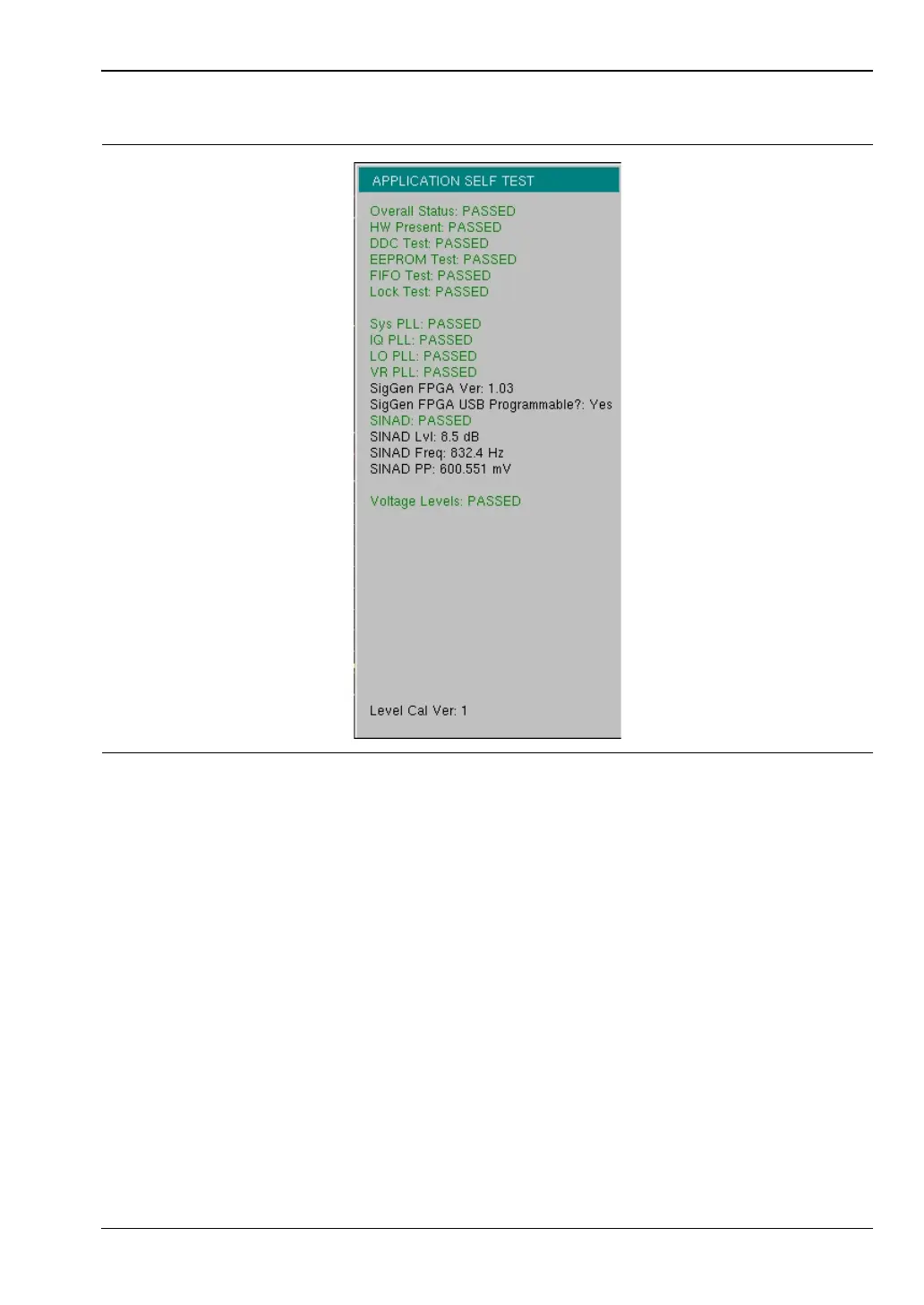
NBFM, P25/P25p2, NXDN
, dPMR, DMR 2, PTC,
and TETRA Self T
est
Figure
B-5.
Application Self T
est
128
130
Table of Contents
Main Page
Default Chapter
3
Table of Contents
3
Chapter 1-General Information
9
Introduction
9
Additional Documentation
9
Contacting Anritsu for Sales and Service
10
Instrument Description
11
Available Models
11
Additional Options
12
Instrument Care and Preventive Maintenance
13
Connector Care
13
ESD Caution
14
Battery Replacement
14
Calibration and Verification
16
Secure Environment Workplace
17
LMR Master Memory Types
17
Erase All User Files in Internal Memory
17
Recommended Usage in a Secure Environment
18
Chapter 2-Instrument Overview
19
Introduction
19
Turning on the LMR Master
19
Front Panel Overview
19
Front Panel Keys
21
S412E UG PN: 10580-00318 Rev. P
23
Touch Screen Keys
24
Keypad Menu Keys (1 to 9)
24
LED Indicators
24
Display Overview
25
Display Settings
26
Test Panel Connector Overview
27
Test Panel Connectors
28
Symbols and Indicators
29
Battery Symbols
31
Additional Symbols
32
Data Entry
32
Numeric Values
32
Parameter Setting
32
Text Entry
33
Mode Selector Menu
34
Soft Carrying Case
35
2-10 Tilt Bail Stand
36
Chapter 3-Quick Start Guide
37
Introduction
37
Measurement Mode Selection
37
CW Signal Generator
38
Vector Network Analyzer
39
Field Mode Display Vs. Standard VNA Display
39
Select the Measurement Type
40
Set the Frequency
40
Set the Scale
40
Turn on Markers
40
Peak and Valley Search Markers
40
Set up Delta Markers
41
Set a Single Limit Line
41
Set up Distance Domain
42
Calibration Considerations
42
Spectrum Analyzer
45
Set Start and Stop Frequencies
45
Enter the Center Frequency
45
Select a Signal Standard
45
Set the Measurement Bandwidth
45
Set the Amplitude
46
Power Offset Set up for Compensating External Loss
46
Set the Span
46
Single Limit Line
47
Create a Limit Envelope
47
Setting up Markers
48
Select a Smart Measurement Type
49
NBFM Analyzer
50
Set the Receiver (Rx) Frequency
50
Set the Signal Source Transmit (Tx) Frequency
50
Rx and Tx Power Offset
51
Select the Measurement Types
51
LMR Digital Demodulation Signal Analyzers
53
Set the Receiver (Rx) Frequency
53
Set the Signal Source Transmit (Tx) Frequency
53
Rx and Tx Power Offset
54
Select the Measurement Types
54
Saving Measurements
59
External Power on
60
Chapter 4-File Management
61
Introduction
61
File Types
61
Managing Files
62
Save Files
62
Save Dialog Box
63
Quick Name Keys
63
Recall Files
64
Recall Dialog Box
64
Copy Files
65
Delete Files
66
Delete Dialog Box
66
File Menu Overview
67
File Menu
68
Save Menu
69
Save Location Menu
70
Save on Event Menu
71
Recall Menu
72
Copy Menu
73
Delete Menu
74
Chapter 5-System Operations
75
Introduction
75
System Menu Group Overview
76
System Menu Map 1
77
System Menu Map 2
77
System Menu
78
Application Options Menu
79
VNA Mode
79
SPA Mode
80
DMR 2 Mode
81
P25 Mode
81
P25P2 Mode
82
NXDN Mode
82
PTC Mode
83
TETRA Mode
83
Updating Signal Generator Patterns
84
System Options Menu
85
System Options 2/2 Menu
86
Power-On Menu
88
Display Settings Menu
89
Reset Menu
90
Preset Menu
91
Self Test
91
5-10 Updating the LMR Master Firmware
92
Chapter 6-Ethernet Connectivity
93
Introduction
93
Ethernet Connection
93
Network Connection
93
Ethernet Direct Connection
93
Ethernet Configuration on the LMR Master
94
LAN Connection
94
Ethernet Config
96
Ethernet Menu
97
Dhcp
98
Example 1
99
Example 2
99
Ipconfig Tool
99
Ping Tool
100
Chapter 7-Anritsu PC Software Tools
101
Introduction
101
Anritsu Tool Box
101
Line Sweep Tools
102
Master Software Tools
103
Easymap Tools
104
Chapter 8-Bias Tee (Option 10)
105
Overview
105
Bias Tee in VNA Mode
105
Bias Tee in SPA Mode
107
Chapter 9-GPS (Option 31)
109
Introduction
109
Activating the GPS Feature
109
Saving and Recalling Traces with GPS Information
111
Saving Traces with GPS Information
111
Recalling GPS Information
111
GPS Menu
111
Chapter 10-Web Remote Control
113
10-1 Introduction
113
10-2 Setup
113
LAN Connection
113
Connection to a Wi-Fi Portable Router
114
10-3 Web Remote Control Interface
116
Menu Bar
118
Remote Control
119
File List
121
Device Management
121
Logout
122
Appendix A-Measurement Guides
123
A-1 Introduction
123
A-1 Introduction
124
Appendix B-Error Messages
125
Introduction
125
Reset Options
125
Reset Via Instrument Menus
125
Reset from off Condition
125
B-1 Introduction
125
Self Test
126
Application Self Test
127
VNA Mode Self Test (Vector Network Analyzer Mode Only
127
Spectrum Analyzer Mode Self Test
128
CW Signal Generator Mode Self Test
128
NBFM, P25/P25P2, NXDN, Dpmr, DMR 2, PTC, and TETRA Self Test
129
Operation Error Messages
130
Fan Failure
130
High Temp Warning
130
Operation Not Permitted in Recall Mode
131
Power Supply
131
Error Saving File. General Error Saving File
131
C-1 Introduction
133
D-1 Introduction
135
Other manuals for Anritsu S412E
Maintenance Manual
122 pages
Related product manuals
Anritsu LMR Master S412E
704 pages
Anritsu Site Master S113B
76 pages