S412E UG PN: 10580-00318 Rev. P 3-1
Chapter 3 — Quick Start Guide
3-1 Introduction
This chapter provides a brief overview of basic measurement setups for several measurement
modes. For detailed measurement information, refer to a specific measurement guide listed in
Appendix A, “Measurement Guides”. This chapter provides quick start measurement
information for the following measurement modes:
• Section 3-3 “CW Signal Generator” on page 3-2
• Section 3-4 “Vector Network Analyzer” on page 3-3
• Section 3-5 “Spectrum Analyzer” on page 3-9
• Section 3-6 “NBFM Analyzer” on page 3-14
• Section 3-7 “LMR Digital Demodulation Signal Analyzers” on page 3-17
3-2 Measurement Mode Selection
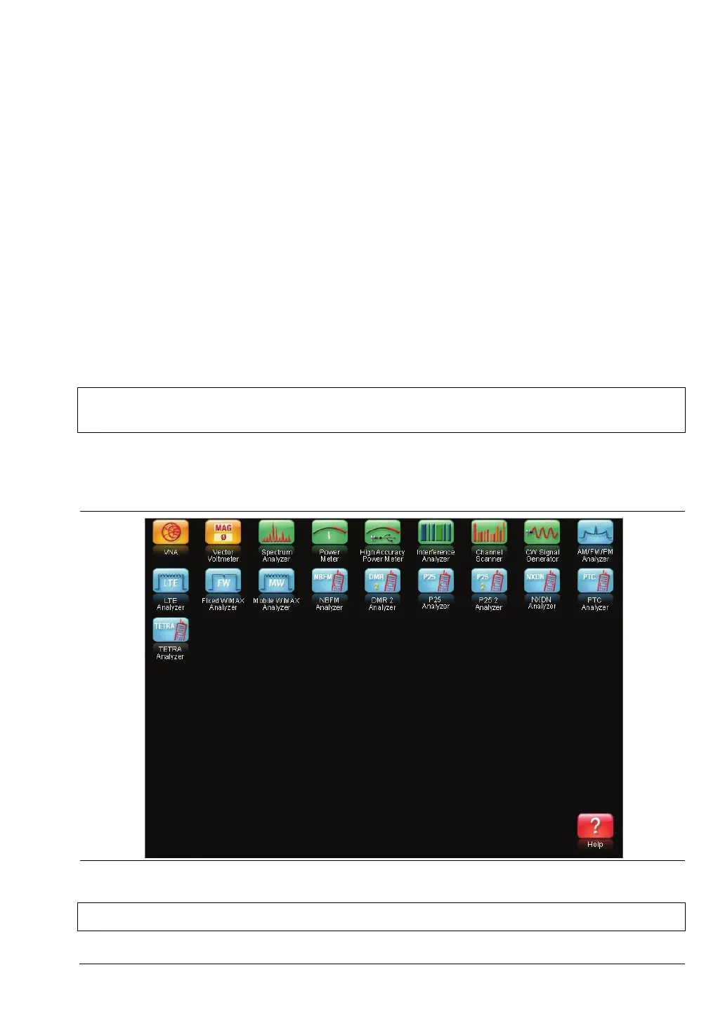
Press the Menu key and use the touch screen to select the appropriate measurement icon.
Note
LMR Digital Demodulation Signal Analyzers include P25/P25p2, NXDN™, dPMR,
DMR 2, ITC-R PTC, and TETRA Signal Analyzers.
Figure 3-1. Menu Screen with Icons for Installed Measurement Modes
Note The display of the Menu screen varies depending on installed options.