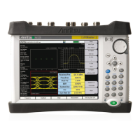
Instrument Overview 2-6 Symbols and Indicators
S412E UG PN: 10580-00318 Rev. P 2-11
External Trigger In
A TTL signal that is applied to the External Trigger In female BNC input connector causes a
single sweep to occur. In the Spectrum Analyzer mode, it is used in zero span, and triggering
occurs on the rising edge of the signal. After the sweep is complete, the resultant trace is
displayed until the next trigger signal arrives (refer to item “3” in Figure 2-8).
External Reference In
The BNC female connector (refer to item “1” in Figure 2-8) is used for connection of an
external frequency reference. The amplitude of the External Reference should be between
–10 dBm and +10 dBm.
RF In (50 ohm)
This connector (refer to item “5” in Figure 2-8) provides the input 50 ohm interface for the
Spectrum Analyzer function. With Option 10, Bias Tee, output is available on the center pin
out of this port in Spectrum Analyzer mode.
GPS Antenna Connector (Option 31)
The GPS antenna connection on the LMR Master is type SMA-female (refer to item “6” in
Figure 2-8). The GPS function is described in Chapter 9, “GPS (Option 31) ”.
Audio In
Audio In (refer to item “2” in Figure 2-8) is used to support SINAD and Quieting
measurements of analog FM radio sensitivity.
Signal Generator Out
Output of the built-in Signal Generator when the LMR Master is in CW, NBFM, P25/P25p2,
NXDN, dPMR, DMR 2, TETRA, or PTC mode (refer to item “4” in Figure 2-8). Output is
turned on with the Turn Sig-Gen ON main menu key.
VNA Port-1 (50 ohm)
This connector (refer to item “12” in Figure 2-8) provides the input/output 50 ohm interface
for reflection measurements of the Vector Network Analyzer at Port 1.
VNA Port-2 (50 ohm)
This connector (refer to item “13” in Figure 2-8) provides the input 50 ohm interface for
transmission measurements of the Vector Network Analyzer at Port 2. With Option 10,
Bias Tee, output is available on the center pin out of this port in VNA mode.
2-6 Symbols and Indicators
The following symbols and indicators indicate the instrument status or condition on the
display.