Patient monitor User’s manual
Chapter 7-6
When using the ESU device, avoid placing the electrodes near the ESU
grounding pad, otherwise, grate deal interference will influence the
ECG signals. The monitor should be placed far from the operating
table. Power wires and the ECG cables should be partitioned and
should not be in parallel.
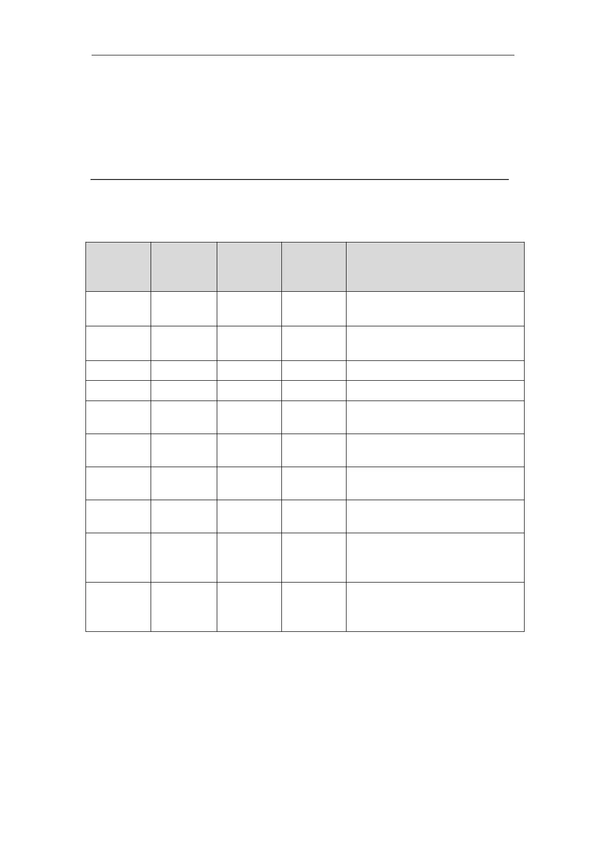
The following table shows the ECG electrode label to identify each
electrode and its associated color of AHA and IEC standards.
Directly below the clavicle and
near the right shoulder
Directly below the clavicle and
near the left shoulder
On the right lower abdomen
On the left lower abdomen
On the fourth intercostal space
at the right sternal border
On the fourth intercostal space
at the left sternal border
Midway between the V2 and
V4 electrode positions
On the fifth intercostal space at
the left midclavicular line
On the left anterior axillary
line, horizontal with the V4
electrode position
On the left midaxillary line,
horizontal with the V4
electrode position
7.3.3 Connecting ECG Cable
Plug the ECG cable into the ECG connector on the EMS. An ECG waveform
and numeric appears on the monitor display.
Depending on the patient to be monitored, you shall select the proper leads