Input definition – type Internal
(INPUT/OUTPUT, 1, )
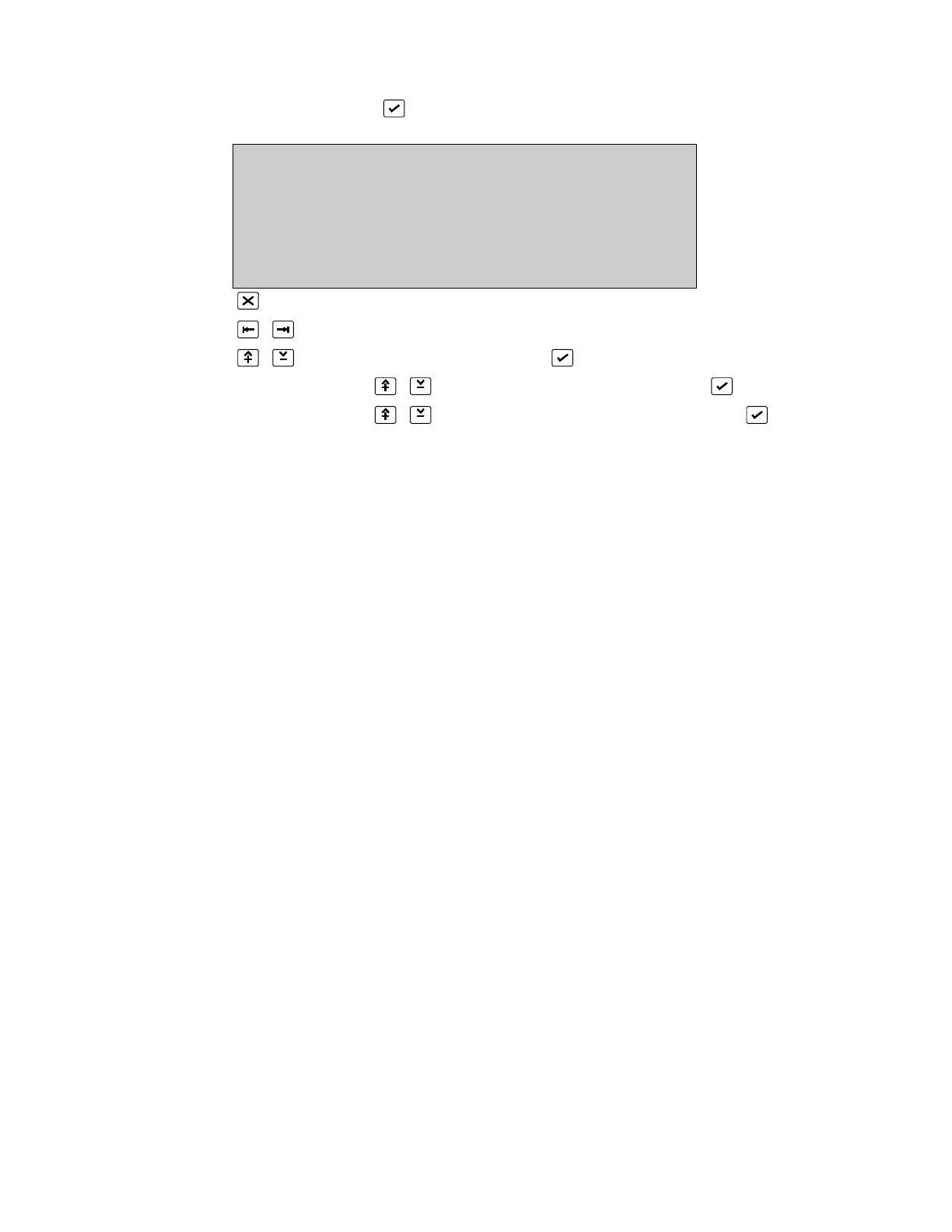
INPUT DEFINITION State :false
Input :1 Trig. :latched
Type :Internal Mode :active
Board :24:FEP continuous
Input :1 Event unlogged
0. .9, ^V, <>, E, X
Alarms: 0 Faults: 0 Cond.: 0 P: 1 SDZ
Return to Input/Output Menu Page 109
Place cursor at TYPE
Select Type: INTERNAL and press (Unlock memory!)
Use number 0..9 or to select PC Board address and press
Use number 0..9 or to select PC Board input number and press
*See Common Facilities - All Input Types, Page 111 for a description of Input, State,
Trigger, Mode, Event and Text
The input number selected is assigned to a physical electrical input provided on a printed
circuit board within the FP2000 fire panel. In order to assign a physical input, the PC
Board address (see Page 32 for board addressing) as well as the input number on that
board must be defined. For example: the FP2000 provides four inputs on the FEP board
(address 24) as standard.
This screen confirms the PC Board type when the board address is entered.
Trigger: Latched/Unlatched
Mode: Passive/Active/Open/Short/Active1/Abnormal
Continuous/Pulse
Event: Unlogged/Logged/Fire/Fault/Condition
Text: Allowed
* See Input Description in the Serial Communication Format

 Loading...

