Automatic Divider-rounder model Syncro
18/79
Use and maintenance manual (translation of the original instructions) - MASA6_en_2 of 23/03/2021
3 INSTALLATION AND USE
3.1 INSTALLATION ROOM REQUIREMENTS
The place where the machine will be kept and/or used must conform to the current laws in force and ensure
adequate protection from impacts, damage, deterioration and atmospheric agents. The dimensions and
characteristics of the access points must allow the easy and safe passage of the machine without people or the
machine itself being put at risk. The characteristics of the flooring, load-bearing structures and walls must
comply with the laws and regulations in force, also in consideration of the total load to be withstood and the
relative safety coefficients; they must be easy to clean, disinfect and disinfest. The floor must be flat, not
sloping, compact, without holes and roughness. The electrical system and the equipotential protection system
(earth) of the site must conform to the laws and standard currently in force, and must be constructed,
maintained and, if required by law, verified by authorized and professionally qualified technicians accredited to
issue the relative declarations of conformity. The upstream power supply panel must have suitable protection
devices against overloads, short-circuit, phase-phase, phase-neutral (if applicable), and phase-earth
malfunctions.
3.2 TRANSPORT, HANDLING AND POSITIONING
Depending on the destination and the contractual agreements, the machine is sent wrapped with protective
plastic material, or (in the case of sea freight) in a “barrier bag” and closed in a wooden crate firmly blocked to
the base of the same.
The load is blocked on the surface of the means of transport with crossbars and/or wooden blocks suitably
positioned to prevent it from moving during transport; the load must also be tied from 2/3 of the total height of
the wooden crate upward to points on the means of transport that are sufficiently resistant to prevent it from
overturning.
For handling the load packed in the wooden crate, use a forklift truck with a capacity adequate for the
mass (see par. 2.2,Table 1 ); insert the forks inside the lower wooden crossbars and as close as
possible to them, so as to prevent unwanted movement to the sides; the forks of the forklift must protrude
by at least 200 mm from the other side
The pallet lifting area is accessible by the forks from the special
opening on the sides of the pallet Figure 7.
Remove the sides of the crate (just unscrew the boards, paying
attention to the protruding nails) and free the machine from the
wrapping (stretch plastic film or barrier bag). Separate the
materials by type (plastic, wood, etc.) and take them to dedicated
places, accessible only to authorized persons, pending disposal
by specialized companies, which must take place in compliance
with any laws in force on the subject (also the wooden base must
be treated in the same way once the machine has been removed
from it).
In Italy and other States, especially within the European
Union, waste disposal according to precise rules and
respect for the environment are obligations unequivocally
established by the applicable legislation.
Make sure that the machine is intact in every part; in case of
doubt, contact the manufacturer.
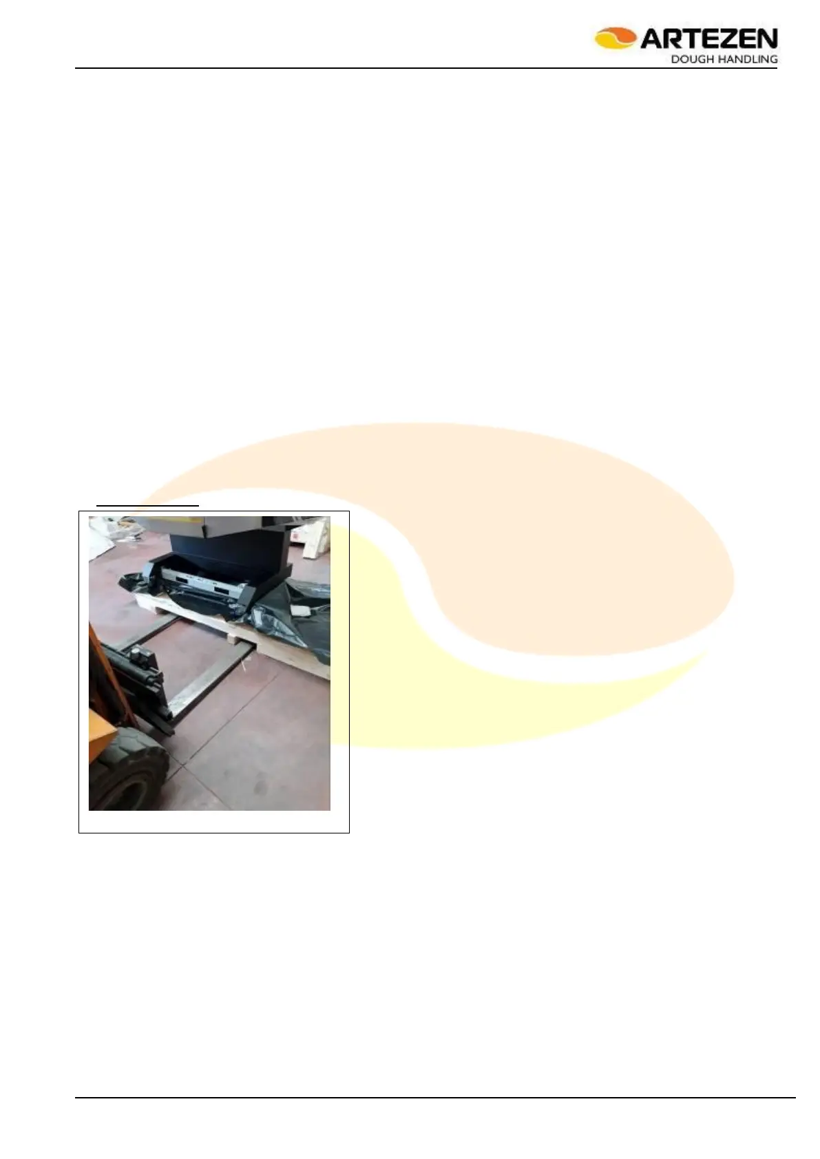
With reference to Figure 8, to release the machine from the
wooden base on which it is blocked proceed as follows:
wear abrasion-resistant gloves, helmet, shoes with
reinforced toe and anti-puncture outsole
use a forklift to stabilize the machine in its resting
position on the transport pallet: the forks of the forklift must be inserted into the rectangular slots placed
both on the front of the machine and on the rear. Make sure that the forks of the truck protrude on the
opposite side by at least 200 mm from the machine profile
Unscrew the nuts at the top of the threaded rods visible in Figure 8 ref. A and B, then take out the
threaded rods. A 19 mm hex wrench is sufficient to unscrew the threaded nut. If the threaded rod
rotates around itself while loosening the nut during unscrewing, which would make any attempt to
remove the threaded nut vain, just use a pair of pliers to stop it from rotating.
Next, unscrew the threaded nut locking the machine to the pallet, located on the rear side Figure 8 ref.
C, then pull out the threaded rod. A 19 mm hex wrench is sufficient to unscrew the threaded nut. If the
threaded rod rotates around itself while loosening the nut during unscrewing, which would make any
attempt to remove the threaded nut vain, just use a pair of pliers to stop it from rotating.
Figure 7 - Pallet lifting with access for
the forklift forks