Automatic Divider-rounder model Syncro
60/79
Use and maintenance manual (translation of the original instructions) - MASA6_en_2 of 23/03/2021
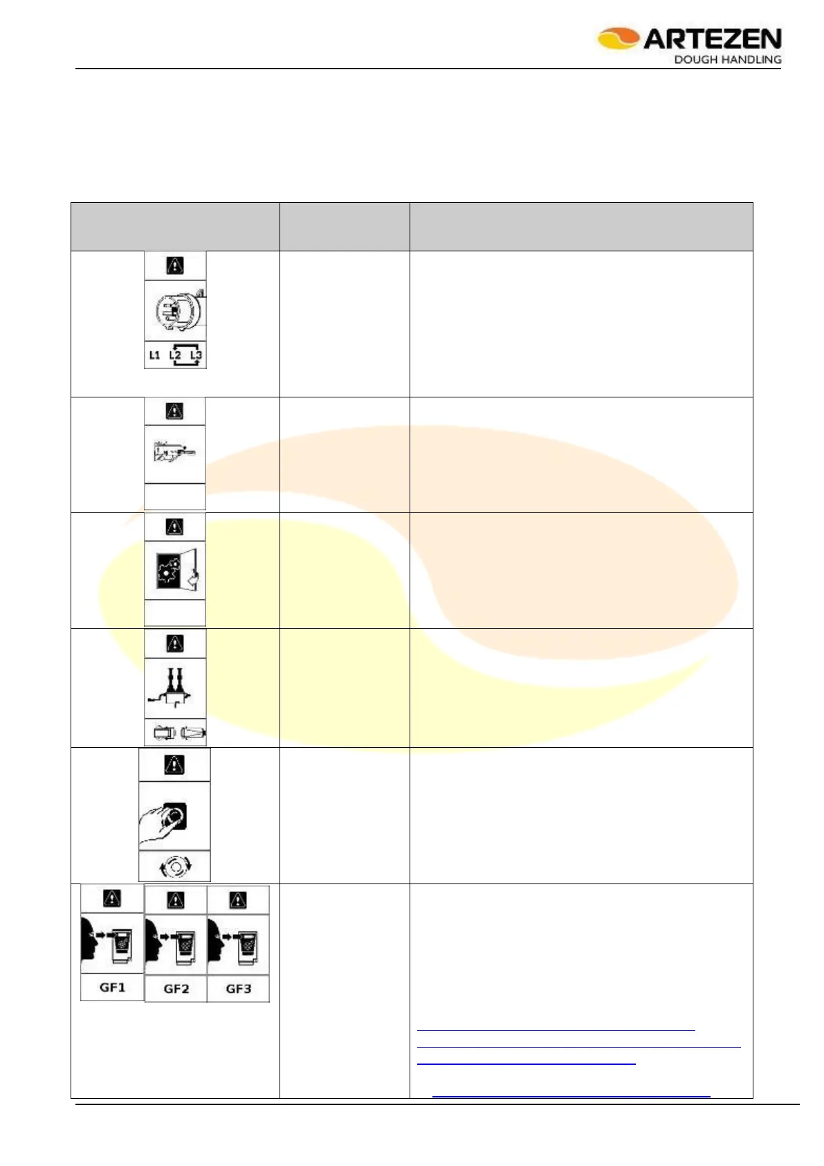
4.8 DIAGNOSTIC SIGNALS - ALARMS
The alarm tables are illustrated here below. Consult Table 10 dedicated to the explanation of the graphic
alarms, which are usually easy to resolve, for example by closing an interlocked door, or releasing the
EMERGENCY STOP push-button. Also consult the
Table 11 dedicated to the explanation of the alarms that are usually more difficult to resolve, which are coded
with a number, in order to facilitate their communication and identification by the technician on site, who may be
in contact with a manufacturer's technician for remote assistance.
DESCRIPTION
OF THE
PROBLEM
Incorrect power
supply phases
Check that the plug has not been moved to a
socket other than the one normally used for
connection: if necessary, return the plug to its original
position;
Check that the connection cable is intact and
free from cuts and abrasions: if necessary,
completely replace the power cable, with an
equivalent type, with the same insulation class and
cross-section.
Dough outfeed
guard open or
triggered.
Close the guard;
Check the mobility of the guard up to the
correct working position;
Check that the limit switch that reads the
position of the guard is in good working order.
Check wire 702 in terminal block "M6", input
in "A1" "I12"
At least one of the
internal machine's
access doors is
open
Close all doors.
Check that the limit switch that reads the
position of the guard is in good working order.
Check that the coupling of the safety limit
switch to the safety device is correct;
Check wire 605 in terminal block "M6", input
in "A1" "I5"
Dough removing
rollers not
electrically
connected.
Par. 4.4.5;
Check the contacts of the the electrical
system connector.
Emergency stop
push-button
pressed.
Par. 3.10;
Check the internal efficiency of the push-
button’s contacts;
Check wire 603 in terminal block "M6", input
in "A1" "I3"
Alarm in one of
the frequency
converters marked
with “GF1”, “GF2”,
“GF3” inside the
electrical box.
Missing one power supply phase “T”;
Fuse “F1” interrupted - replace it;
Fuse “F4” interrupted - replace it;
Turn off the machine, open the rear electrical
box, then restart the machine: when the problem
reoccurs, check the type of alarm on the display of
the alarmed device by reading the alphanumeric
code. For GF1, consult the following website:
http://www.global-download.schneider-
electric.com/852575A6007E5FD3/all/FF63D5B
6E2EEF644852576B1006F011E
For all other GF2, GF3, etc. go
to:http://www.global-download.schneider-