Automatic Divider-rounder model Syncro
32/79
Use and maintenance manual (translation of the original instructions) - MASA6_en_2 of 23/03/2021
3.8 STARTING OF PROCESSING
3.8.1 STARTING A PRE-DEFINED PROCESSING
Use “I-DRIVE” par. 2.4ref. 9, to scroll through the list of programs among those visible on the display: as
shown in the image in par.3.7.2 Figure 15 where, for example, the program "01-Pgm 30 gr” is
highlighted
Press “I-DRIVE” par. 2.4 ref. 9 to select the highlighted program.
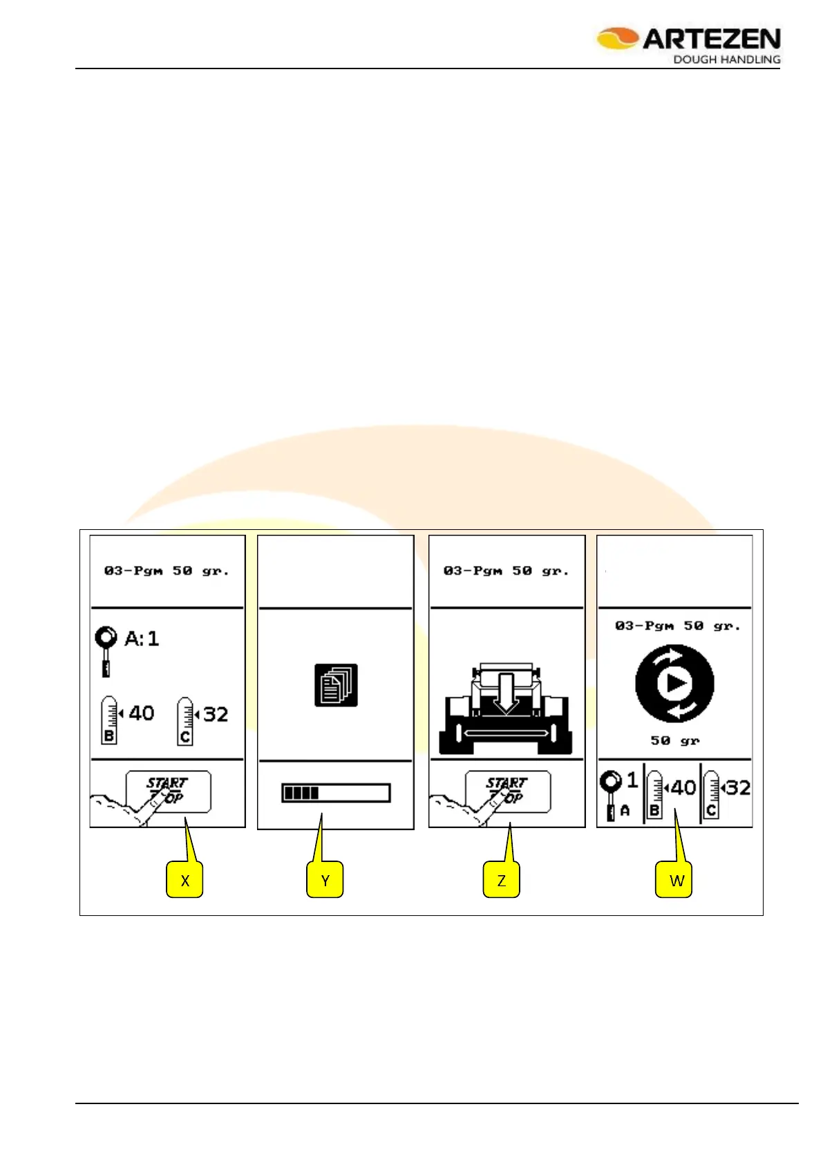
The display will show the “X” image in Figure 22 , and the machine will wait for the START button to be
pressed par. 2.4ref. 8 to start the automatic adjustment set-up according to the selected program. In the
same “X” image, based on the selected program and the stored data, the display also shows the manual
setting of the machine's loaf moulder (only for the “SYNCRO M” and “SYNCRO EM” versions - as
illustrated in par. 3.7.5 in Figure 19 as regards lever ref. 1, lever ref. 2 blocked by lever ref. 3, lever 4
blocked by lever 5).
By pressing the "START" button2.4 ref. 8 the machine starts the automatic set-up with all the internal
adjustments necessary to carry out the selected program, while the display will show the image "Y" in
Figure 22 ;
After a few seconds, depending on the selected program, the display will show the “Z” image in Figure
22 , indicating that the machine is ready to start working. The display also shows the loading hopper, as
a reminder that it is necessary to insert the dough into the hopper in order to start processing.
By pressing the "START" button again2.4 ref. 8, the machine will start working and the display will show
the “W” image in Figure 22 with the central circular icon on the display in rotary simulation, to indicate
that the machine is working. Also in this case, the display will show the manual adjustments to be made
on the loaf moulder (A, B, C), if installed on the machine.
Take some dough from the rack as illustrated in par. 3.7.3and introduce it vertically into the loading
hopper, making sure that the top section of the mash does not protrude from the hopper. If the display
shows the image in Figure 23 , it means that the dough protrudes from the hopper and it is therefore
necessary to lower the level, removing some of it.
Figure 22 - Starting of processing