Model 8640B TM 9-4935-601-14-7&P
PERFORMANCE TESTS
4-28. AUXILIARY OUTPUT TEST (Cont'd)
2. Use generator's FREQUENCY TUNE and RANGE controls to tune from 512 to 0.5 MHz. The power meter
should read >-5 dBm at all frequencies.
-5 dBm_________________
4-29. OUTPUT LEAKAGE TEST
SPECIFICATION:
Leakage: (With all unused outputs terminated properly). Leakage limits are below those specified in MIL-1-6181D.
Furthermore, less than 3 MV is induced in a 2-turn, 1-inch diameter loop 1 inch away from any surface and measured
into a 50Ω receiver.
DESCRIPTION:
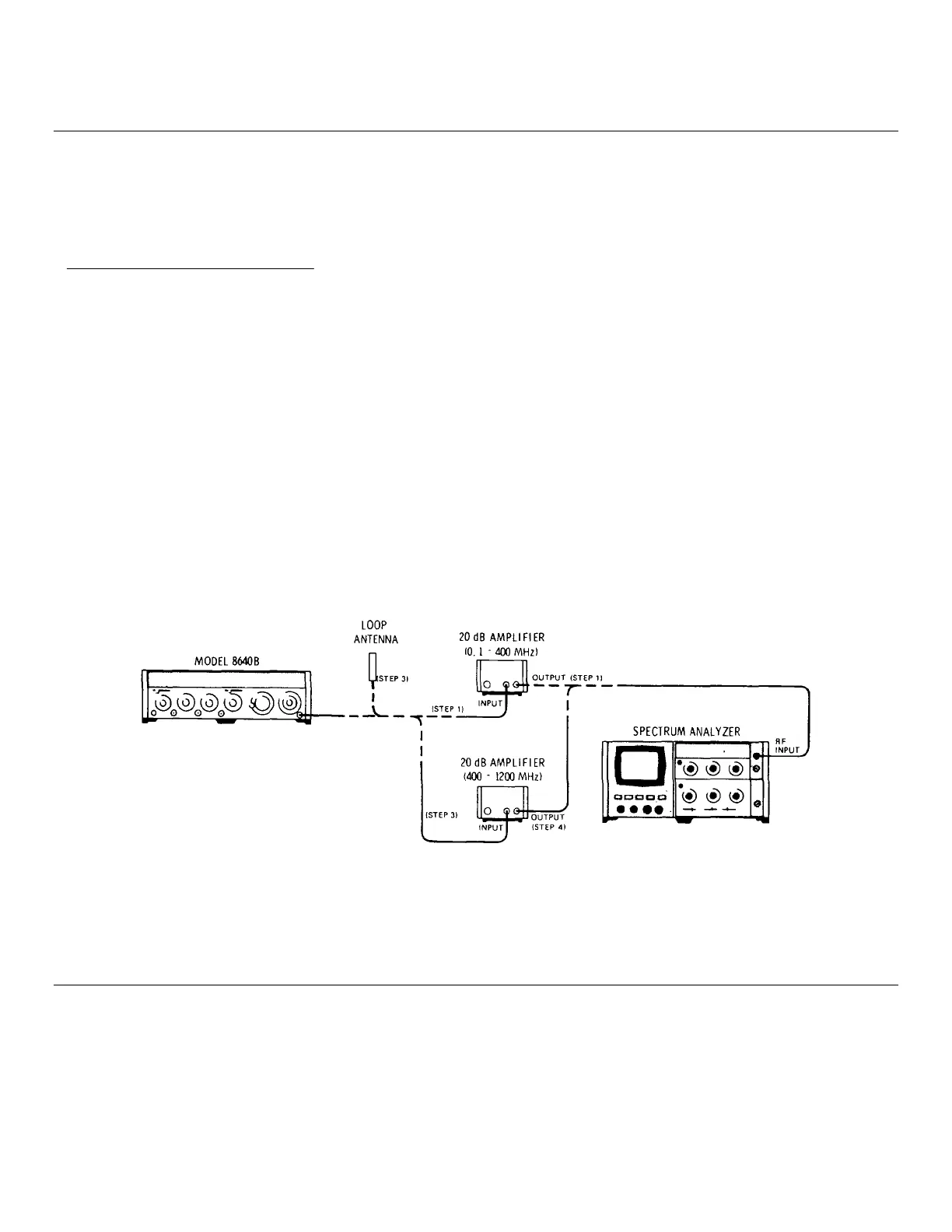
A loop antenna is held one inch from all surfaces of the Signal Generator and any leakage monitored with a spectrum
analyzer. The loop antenna is suspended in a molding so that when the molding is in contact with a surface, the loop
antenna is one inch from the surface.
NOTE
The use of a screen room may be necessary to reduce external radiated interference.
Figure 4-15. Output Leakage Test Setup.
NOTE
To avoid disturbing antenna's field and causing measurement error, grasp antenna at the end
that has the BNC connector.
4-42
Artisan Technology Group - Quality Instrumentation ... Guaranteed | (888) 88-SOURCE | www.artisantg.com