Model 8640B TM 9-4935-601-14-7&P
PERFORMANCE TESTS
4-16. FREQUENCY STABILITY VS LOAD, LEVEL, AND MODE TEST (Cont'd)
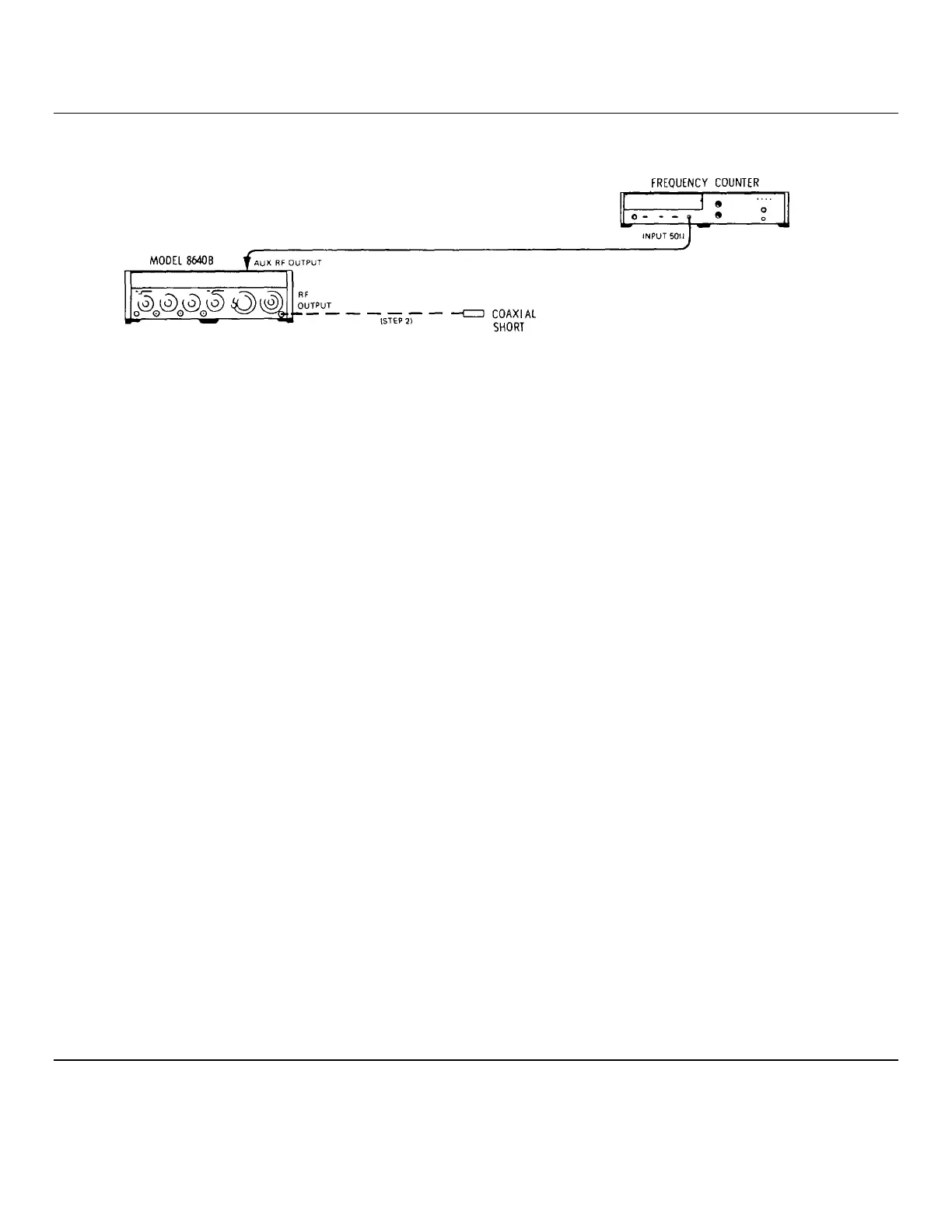
Figure 4-4. Frequency Stability us Load, Level, and Mode Test Setup
EQUIPMENT:
Frequency Counter.................................................................................................. HP 5327C
Type N Male Coaxial Short.....................................................................................HP 11512A
PROCEDURE:
1. Connect equipment as shown in Figure 4-4 after setting Signal Generator's controls as follows:
COUNTER MODE: EXPAND...................................................................................Off
LOCK........................................................................................Off
Source ..................................................................................... INT
AM............................................................................................................................................................OFF
FM............................................................................................................................................................OFF
RANGE ..........................................................................................................................................32-64 MHz
FREQUENCY TUNE ...........................................................................................................................50 MHz
OUTPUT LEVEL................................................................................................................................+19 dBm
RF ON/OFF................................................................................................................................................ON
2. Note frequency counter reading. Then connect coaxial short to RF OUTPUT. Again, note frequency counter
reading. It should have changed less than 50 Hz.
___________________________ 50 Hz
3. Remove coaxial short, note frequency counter reading, then set OUTPUT LEVEL vernier to +9 dBm. Again, note
frequency counter reading. It should have changed less than 50 Hz.
___________________________ 50 Hz
4. Set RANGE to 256 - 512 MHz, and set FREQUENCY TUNE to 500 MHz. With FM switch set to OFF, note the
frequency counter reading. Set PEAK DEVIATION switch to 10 kHz and PEAK DEVIATION vernier full clockwise.
Set FM to AC and again, note frequency counter reading. It should have changed less than 200 Hz.
__________________________ 200 Hz
4-10
Artisan Technology Group - Quality Instrumentation ... Guaranteed | (888) 88-SOURCE | www.artisantg.com