Model 8640B TM 9-4935-601-14-7&P
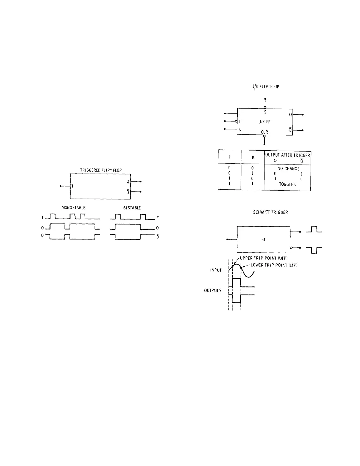
8-44. Triggered Flip-Flop. There are two kinds of
triggered flip-flops. The bistable triggered flip-flop
toggles (changes states) each time the trigger input (T)
changes states (shown in Figure 8-4). This effectively
divides the input by two, giving one output pulse at the
Q output for every two input pulses.
8-45. The monostable triggered flip-flop's Q output goes
high when triggered by the T input. However, after a set
amount of time (determined either by the flip-flop's
configuration or unless retriggered) the Q output
automatically returns to its original state. The
monostable flip-flop (or one shot) is used to stretch or
shape pulses.
Figure 8-4. Triggered Flip-Flop
8-46. D Flip-Flop. The D-type flip-flop, shown in
Figure 8-5, is used as a storage latch or buffer. The
information at the data input (D) is transferred to the Q
output when the trigger input (T) is high-going. Once
the T input has passed its threshold, the D input is
locked out and the Q outputs do not change until
another high-going transition occurs at the T input.
8-47. The set (S) and clear (CLR) inputs override all
other input conditions: when set is low, the Q output is
forced high; when clear is low, the Q output is forced
low. Although normally the Q output is the compliment
of the Q output, simultaneous low inputs at S and CLR
will force both Q and Q high on some D flip-flops.
8-48. Schmitt Trigger. A typical Schmitt Trigger is
shown in Figure 8-6. Some Schmitt triggers have
complementary outputs. The device initially triggers
when the input signal passes a voltage reference called
the upper trip point. It triggers back into its initial state
when the input voltage passes a voltage reference
called the lower trip point. One or both trip points may
be indicated.
Figure 8-5. D-Flip-Flop
Figure 8-6. Schmitt Trigger
8-49. J/K Flip-Flop. Figure 8-7 shows a typical J/K
flip-flop. The trigger (T) input is activated by a low-
going signal as indicated by the circle on the symbol.
Flip-flop response is determined by the values of the J
and K inputs at the instant that a low-going signal is
applied to the trigger input:
a. When J and K are low, the Q outputs will not
change state.
8-7
Artisan Technology Group - Quality Instrumentation ... Guaranteed | (888) 88-SOURCE | www.artisantg.com